CN114725317A - Electrochemical process for gas separation - Google Patents
Electrochemical process for gas separation Download PDFInfo
- Publication number
- CN114725317A CN114725317A CN202210357090.4A CN202210357090A CN114725317A CN 114725317 A CN114725317 A CN 114725317A CN 202210357090 A CN202210357090 A CN 202210357090A CN 114725317 A CN114725317 A CN 114725317A
- Authority
- CN
- China
- Prior art keywords
- electroactive
- negative electrode
- species
- electrochemical cell
- positive electrode
- Prior art date
- Legal status (The legal status is an assumption and is not a legal conclusion. Google has not performed a legal analysis and makes no representation as to the accuracy of the status listed.)
- Pending
Links
- 238000000034 method Methods 0.000 title claims abstract description 84
- 238000000926 separation method Methods 0.000 title claims abstract description 51
- 230000008569 process Effects 0.000 title description 15
- 239000011264 electroactive composite Substances 0.000 claims description 53
- CURLTUGMZLYLDI-UHFFFAOYSA-N Carbon dioxide Chemical compound O=C=O CURLTUGMZLYLDI-UHFFFAOYSA-N 0.000 claims description 44
- 229910002092 carbon dioxide Inorganic materials 0.000 claims description 43
- OKTJSMMVPCPJKN-UHFFFAOYSA-N Carbon Chemical compound [C] OKTJSMMVPCPJKN-UHFFFAOYSA-N 0.000 claims description 36
- 239000000463 material Substances 0.000 claims description 31
- 239000002131 composite material Substances 0.000 claims description 30
- 230000002829 reductive effect Effects 0.000 claims description 28
- 238000007600 charging Methods 0.000 claims description 26
- 229910052799 carbon Inorganic materials 0.000 claims description 23
- 230000000295 complement effect Effects 0.000 claims description 23
- 229920006395 saturated elastomer Polymers 0.000 claims description 20
- 239000001569 carbon dioxide Substances 0.000 claims description 19
- 239000002608 ionic liquid Substances 0.000 claims description 17
- 239000003575 carbonaceous material Substances 0.000 claims description 16
- 229920000642 polymer Polymers 0.000 claims description 15
- 239000007788 liquid Substances 0.000 claims description 12
- 239000002041 carbon nanotube Substances 0.000 claims description 8
- 229910021393 carbon nanotube Inorganic materials 0.000 claims description 7
- 239000006229 carbon black Substances 0.000 claims description 5
- 229910021389 graphene Inorganic materials 0.000 claims description 5
- 238000004891 communication Methods 0.000 claims description 4
- 239000012530 fluid Substances 0.000 claims description 4
- 239000013543 active substance Substances 0.000 claims 3
- 239000000203 mixture Substances 0.000 abstract description 10
- 238000002848 electrochemical method Methods 0.000 abstract 1
- 241000894007 species Species 0.000 description 187
- 239000007789 gas Substances 0.000 description 139
- 239000010410 layer Substances 0.000 description 89
- 208000028659 discharge Diseases 0.000 description 29
- 238000006243 chemical reaction Methods 0.000 description 24
- 239000011263 electroactive material Substances 0.000 description 20
- 239000013076 target substance Substances 0.000 description 15
- 238000006722 reduction reaction Methods 0.000 description 14
- 230000009467 reduction Effects 0.000 description 13
- ZMXDDKWLCZADIW-UHFFFAOYSA-N N,N-Dimethylformamide Chemical compound CN(C)C=O ZMXDDKWLCZADIW-UHFFFAOYSA-N 0.000 description 12
- 239000003792 electrolyte Substances 0.000 description 12
- 238000007254 oxidation reaction Methods 0.000 description 12
- 238000010586 diagram Methods 0.000 description 11
- 230000003647 oxidation Effects 0.000 description 11
- 239000011829 room temperature ionic liquid solvent Substances 0.000 description 10
- 239000000758 substrate Substances 0.000 description 10
- 239000002048 multi walled nanotube Substances 0.000 description 8
- IJGRMHOSHXDMSA-UHFFFAOYSA-N Atomic nitrogen Chemical compound N#N IJGRMHOSHXDMSA-UHFFFAOYSA-N 0.000 description 7
- 238000010521 absorption reaction Methods 0.000 description 7
- HEDRZPFGACZZDS-UHFFFAOYSA-N Chloroform Chemical compound ClC(Cl)Cl HEDRZPFGACZZDS-UHFFFAOYSA-N 0.000 description 6
- 238000010893 electron trap Methods 0.000 description 6
- 239000011148 porous material Substances 0.000 description 6
- 125000006850 spacer group Chemical group 0.000 description 6
- 239000000126 substance Substances 0.000 description 6
- IQQRAVYLUAZUGX-UHFFFAOYSA-N 1-butyl-3-methylimidazolium Chemical compound CCCCN1C=C[N+](C)=C1 IQQRAVYLUAZUGX-UHFFFAOYSA-N 0.000 description 5
- RAHZWNYVWXNFOC-UHFFFAOYSA-N Sulphur dioxide Chemical compound O=S=O RAHZWNYVWXNFOC-UHFFFAOYSA-N 0.000 description 5
- 150000004056 anthraquinones Chemical class 0.000 description 5
- 239000004020 conductor Substances 0.000 description 5
- 238000007599 discharging Methods 0.000 description 5
- 238000002474 experimental method Methods 0.000 description 5
- 239000004744 fabric Substances 0.000 description 5
- 238000006479 redox reaction Methods 0.000 description 5
- -1 1-butyl-3-methylimidazolium tetrafluoroborate Chemical compound 0.000 description 4
- PYKYMHQGRFAEBM-UHFFFAOYSA-N anthraquinone Natural products CCC(=O)c1c(O)c2C(=O)C3C(C=CC=C3O)C(=O)c2cc1CC(=O)OC PYKYMHQGRFAEBM-UHFFFAOYSA-N 0.000 description 4
- UORVGPXVDQYIDP-UHFFFAOYSA-N borane Chemical compound B UORVGPXVDQYIDP-UHFFFAOYSA-N 0.000 description 4
- 230000008859 change Effects 0.000 description 4
- KTWOOEGAPBSYNW-UHFFFAOYSA-N ferrocene Chemical compound [Fe+2].C=1C=C[CH-]C=1.C=1C=C[CH-]C=1 KTWOOEGAPBSYNW-UHFFFAOYSA-N 0.000 description 4
- 238000012545 processing Methods 0.000 description 4
- 230000036647 reaction Effects 0.000 description 4
- 239000000243 solution Substances 0.000 description 4
- 230000002194 synthesizing effect Effects 0.000 description 4
- 239000002699 waste material Substances 0.000 description 4
- XLYOFNOQVPJJNP-UHFFFAOYSA-N water Substances O XLYOFNOQVPJJNP-UHFFFAOYSA-N 0.000 description 4
- RZVHIXYEVGDQDX-UHFFFAOYSA-N 9,10-anthraquinone Chemical group C1=CC=C2C(=O)C3=CC=CC=C3C(=O)C2=C1 RZVHIXYEVGDQDX-UHFFFAOYSA-N 0.000 description 3
- RYGMFSIKBFXOCR-UHFFFAOYSA-N Copper Chemical compound [Cu] RYGMFSIKBFXOCR-UHFFFAOYSA-N 0.000 description 3
- OKKJLVBELUTLKV-UHFFFAOYSA-N Methanol Chemical compound OC OKKJLVBELUTLKV-UHFFFAOYSA-N 0.000 description 3
- KWYUFKZDYYNOTN-UHFFFAOYSA-M Potassium hydroxide Chemical compound [OH-].[K+] KWYUFKZDYYNOTN-UHFFFAOYSA-M 0.000 description 3
- 239000004809 Teflon Substances 0.000 description 3
- 229920006362 Teflon® Polymers 0.000 description 3
- LSOTZYUVGZKSHR-UHFFFAOYSA-N anthracene-1,4-dione Chemical compound C1=CC=C2C=C3C(=O)C=CC(=O)C3=CC2=C1 LSOTZYUVGZKSHR-UHFFFAOYSA-N 0.000 description 3
- 229920002678 cellulose Polymers 0.000 description 3
- 239000001913 cellulose Substances 0.000 description 3
- 238000002485 combustion reaction Methods 0.000 description 3
- RAXXELZNTBOGNW-UHFFFAOYSA-N imidazole Natural products C1=CNC=N1 RAXXELZNTBOGNW-UHFFFAOYSA-N 0.000 description 3
- 239000003273 ketjen black Substances 0.000 description 3
- VNWKTOKETHGBQD-UHFFFAOYSA-N methane Chemical compound C VNWKTOKETHGBQD-UHFFFAOYSA-N 0.000 description 3
- 229910052757 nitrogen Inorganic materials 0.000 description 3
- 230000001590 oxidative effect Effects 0.000 description 3
- AZQWKYJCGOJGHM-UHFFFAOYSA-N 1,4-benzoquinone Chemical compound O=C1C=CC(=O)C=C1 AZQWKYJCGOJGHM-UHFFFAOYSA-N 0.000 description 2
- 101710134784 Agnoprotein Proteins 0.000 description 2
- 239000006245 Carbon black Super-P Substances 0.000 description 2
- ZRALSGWEFCBTJO-UHFFFAOYSA-N Guanidine Chemical compound NC(N)=N ZRALSGWEFCBTJO-UHFFFAOYSA-N 0.000 description 2
- VEXZGXHMUGYJMC-UHFFFAOYSA-N Hydrochloric acid Chemical compound Cl VEXZGXHMUGYJMC-UHFFFAOYSA-N 0.000 description 2
- YNAVUWVOSKDBBP-UHFFFAOYSA-N Morpholine Chemical compound C1COCCN1 YNAVUWVOSKDBBP-UHFFFAOYSA-N 0.000 description 2
- NQRYJNQNLNOLGT-UHFFFAOYSA-N Piperidine Chemical compound C1CCNCC1 NQRYJNQNLNOLGT-UHFFFAOYSA-N 0.000 description 2
- WTKZEGDFNFYCGP-UHFFFAOYSA-N Pyrazole Chemical compound C=1C=NNC=1 WTKZEGDFNFYCGP-UHFFFAOYSA-N 0.000 description 2
- JUJWROOIHBZHMG-UHFFFAOYSA-N Pyridine Chemical compound C1=CC=NC=C1 JUJWROOIHBZHMG-UHFFFAOYSA-N 0.000 description 2
- KAESVJOAVNADME-UHFFFAOYSA-N Pyrrole Chemical compound C=1C=CNC=1 KAESVJOAVNADME-UHFFFAOYSA-N 0.000 description 2
- 239000011149 active material Substances 0.000 description 2
- 150000001450 anions Chemical class 0.000 description 2
- 230000008901 benefit Effects 0.000 description 2
- 229910000085 borane Inorganic materials 0.000 description 2
- 239000000919 ceramic Substances 0.000 description 2
- 239000013626 chemical specie Substances 0.000 description 2
- 150000001875 compounds Chemical class 0.000 description 2
- 229910052802 copper Inorganic materials 0.000 description 2
- 239000010949 copper Substances 0.000 description 2
- 230000000694 effects Effects 0.000 description 2
- 238000001704 evaporation Methods 0.000 description 2
- 239000010439 graphite Substances 0.000 description 2
- 229910002804 graphite Inorganic materials 0.000 description 2
- 238000011068 loading method Methods 0.000 description 2
- 238000004519 manufacturing process Methods 0.000 description 2
- 229910052751 metal Inorganic materials 0.000 description 2
- 239000002184 metal Substances 0.000 description 2
- 239000002985 plastic film Substances 0.000 description 2
- 229920006255 plastic film Polymers 0.000 description 2
- 239000002861 polymer material Substances 0.000 description 2
- 238000010926 purge Methods 0.000 description 2
- SQGYOTSLMSWVJD-UHFFFAOYSA-N silver(I) nitrate Inorganic materials [Ag+].[O-]N(=O)=O SQGYOTSLMSWVJD-UHFFFAOYSA-N 0.000 description 2
- 239000002109 single walled nanotube Substances 0.000 description 2
- 238000001179 sorption measurement Methods 0.000 description 2
- 238000003860 storage Methods 0.000 description 2
- BFKJFAAPBSQJPD-UHFFFAOYSA-N tetrafluoroethene Chemical compound FC(F)=C(F)F BFKJFAAPBSQJPD-UHFFFAOYSA-N 0.000 description 2
- JRTIUDXYIUKIIE-KZUMESAESA-N (1z,5z)-cycloocta-1,5-diene;nickel Chemical compound [Ni].C\1C\C=C/CC\C=C/1.C\1C\C=C/CC\C=C/1 JRTIUDXYIUKIIE-KZUMESAESA-N 0.000 description 1
- ZXMGHDIOOHOAAE-UHFFFAOYSA-N 1,1,1-trifluoro-n-(trifluoromethylsulfonyl)methanesulfonamide Chemical compound FC(F)(F)S(=O)(=O)NS(=O)(=O)C(F)(F)F ZXMGHDIOOHOAAE-UHFFFAOYSA-N 0.000 description 1
- VYXHVRARDIDEHS-UHFFFAOYSA-N 1,5-cyclooctadiene Chemical compound C1CC=CCCC=C1 VYXHVRARDIDEHS-UHFFFAOYSA-N 0.000 description 1
- 239000004912 1,5-cyclooctadiene Substances 0.000 description 1
- YPJUNDFVDDCYIH-UHFFFAOYSA-M 2,2,3,3,4,4,4-heptafluorobutanoate Chemical compound [O-]C(=O)C(F)(F)C(F)(F)C(F)(F)F YPJUNDFVDDCYIH-UHFFFAOYSA-M 0.000 description 1
- VPPOIATZCIIXJD-UHFFFAOYSA-N 2,3-dichloroanthracene-1,4-dione Chemical compound C1=CC=C2C=C(C(C(Cl)=C(Cl)C3=O)=O)C3=CC2=C1 VPPOIATZCIIXJD-UHFFFAOYSA-N 0.000 description 1
- WUOUBJDINSHIPE-UHFFFAOYSA-N 3-(4-fluorophenyl)thiophene Chemical compound C1=CC(F)=CC=C1C1=CSC=C1 WUOUBJDINSHIPE-UHFFFAOYSA-N 0.000 description 1
- QTBSBXVTEAMEQO-UHFFFAOYSA-M Acetate Chemical compound CC([O-])=O QTBSBXVTEAMEQO-UHFFFAOYSA-M 0.000 description 1
- 229920000178 Acrylic resin Polymers 0.000 description 1
- 239000004925 Acrylic resin Substances 0.000 description 1
- KLSJWNVTNUYHDU-UHFFFAOYSA-N Amitrole Chemical compound NC1=NC=NN1 KLSJWNVTNUYHDU-UHFFFAOYSA-N 0.000 description 1
- QGZKDVFQNNGYKY-UHFFFAOYSA-O Ammonium Chemical compound [NH4+] QGZKDVFQNNGYKY-UHFFFAOYSA-O 0.000 description 1
- BVKZGUZCCUSVTD-UHFFFAOYSA-M Bicarbonate Chemical compound OC([O-])=O BVKZGUZCCUSVTD-UHFFFAOYSA-M 0.000 description 1
- ROFVEXUMMXZLPA-UHFFFAOYSA-N Bipyridyl Chemical compound N1=CC=CC=C1C1=CC=CC=N1 ROFVEXUMMXZLPA-UHFFFAOYSA-N 0.000 description 1
- YLMXBNACRIGGFX-UHFFFAOYSA-N C=1[C-]=NNN=1 Chemical compound C=1[C-]=NNN=1 YLMXBNACRIGGFX-UHFFFAOYSA-N 0.000 description 1
- 229920000049 Carbon (fiber) Polymers 0.000 description 1
- BVKZGUZCCUSVTD-UHFFFAOYSA-L Carbonate Chemical compound [O-]C([O-])=O BVKZGUZCCUSVTD-UHFFFAOYSA-L 0.000 description 1
- 241000448280 Elates Species 0.000 description 1
- CHJJGSNFBQVOTG-UHFFFAOYSA-N N-methyl-guanidine Natural products CNC(N)=N CHJJGSNFBQVOTG-UHFFFAOYSA-N 0.000 description 1
- 229910002651 NO3 Inorganic materials 0.000 description 1
- NHNBFGGVMKEFGY-UHFFFAOYSA-N Nitrate Chemical compound [O-][N+]([O-])=O NHNBFGGVMKEFGY-UHFFFAOYSA-N 0.000 description 1
- ZCQWOFVYLHDMMC-UHFFFAOYSA-N Oxazole Chemical compound C1=COC=N1 ZCQWOFVYLHDMMC-UHFFFAOYSA-N 0.000 description 1
- 229910019142 PO4 Inorganic materials 0.000 description 1
- 239000002033 PVDF binder Substances 0.000 description 1
- OAICVXFJPJFONN-UHFFFAOYSA-N Phosphorus Chemical compound [P] OAICVXFJPJFONN-UHFFFAOYSA-N 0.000 description 1
- 239000004952 Polyamide Substances 0.000 description 1
- ONIBWKKTOPOVIA-UHFFFAOYSA-N Proline Natural products OC(=O)C1CCCN1 ONIBWKKTOPOVIA-UHFFFAOYSA-N 0.000 description 1
- 102100023116 Sodium/nucleoside cotransporter 1 Human genes 0.000 description 1
- 101710123675 Sodium/nucleoside cotransporter 1 Proteins 0.000 description 1
- QAOWNCQODCNURD-UHFFFAOYSA-L Sulfate Chemical compound [O-]S([O-])(=O)=O QAOWNCQODCNURD-UHFFFAOYSA-L 0.000 description 1
- NINIDFKCEFEMDL-UHFFFAOYSA-N Sulfur Chemical compound [S] NINIDFKCEFEMDL-UHFFFAOYSA-N 0.000 description 1
- FZWLAAWBMGSTSO-UHFFFAOYSA-N Thiazole Chemical compound C1=CSC=N1 FZWLAAWBMGSTSO-UHFFFAOYSA-N 0.000 description 1
- DTQVDTLACAAQTR-UHFFFAOYSA-M Trifluoroacetate Chemical compound [O-]C(=O)C(F)(F)F DTQVDTLACAAQTR-UHFFFAOYSA-M 0.000 description 1
- 230000002378 acidificating effect Effects 0.000 description 1
- 230000004913 activation Effects 0.000 description 1
- 239000002156 adsorbate Substances 0.000 description 1
- 125000000217 alkyl group Chemical group 0.000 description 1
- PNEYBMLMFCGWSK-UHFFFAOYSA-N aluminium oxide Inorganic materials [O-2].[O-2].[O-2].[Al+3].[Al+3] PNEYBMLMFCGWSK-UHFFFAOYSA-N 0.000 description 1
- 150000003862 amino acid derivatives Chemical class 0.000 description 1
- 125000000129 anionic group Chemical group 0.000 description 1
- PQJKLTRMSHJEEN-UHFFFAOYSA-N anthracene-1,5-dione Chemical compound O=C1C=CC=C2C=C3C(=O)C=CC=C3C=C21 PQJKLTRMSHJEEN-UHFFFAOYSA-N 0.000 description 1
- SWYXZZAQKFGYFF-UHFFFAOYSA-N anthracene-2,6-dione Chemical compound O=C1C=CC2=CC3=CC(=O)C=CC3=CC2=C1 SWYXZZAQKFGYFF-UHFFFAOYSA-N 0.000 description 1
- 125000003118 aryl group Chemical group 0.000 description 1
- 239000012298 atmosphere Substances 0.000 description 1
- 230000015572 biosynthetic process Effects 0.000 description 1
- 239000003990 capacitor Substances 0.000 description 1
- 239000004917 carbon fiber Substances 0.000 description 1
- 239000002134 carbon nanofiber Substances 0.000 description 1
- BVKZGUZCCUSVTD-UHFFFAOYSA-N carbonic acid Chemical compound OC(O)=O BVKZGUZCCUSVTD-UHFFFAOYSA-N 0.000 description 1
- 150000007942 carboxylates Chemical group 0.000 description 1
- 239000003054 catalyst Substances 0.000 description 1
- 125000002091 cationic group Chemical group 0.000 description 1
- 150000001768 cations Chemical class 0.000 description 1
- 150000005829 chemical entities Chemical class 0.000 description 1
- 239000007795 chemical reaction product Substances 0.000 description 1
- 239000003795 chemical substances by application Substances 0.000 description 1
- 230000006835 compression Effects 0.000 description 1
- 238000007906 compression Methods 0.000 description 1
- 238000001816 cooling Methods 0.000 description 1
- 239000008367 deionised water Substances 0.000 description 1
- 229910021641 deionized water Inorganic materials 0.000 description 1
- SWSQBOPZIKWTGO-UHFFFAOYSA-N dimethylaminoamidine Natural products CN(C)C(N)=N SWSQBOPZIKWTGO-UHFFFAOYSA-N 0.000 description 1
- 239000006185 dispersion Substances 0.000 description 1
- 238000004090 dissolution Methods 0.000 description 1
- 238000001035 drying Methods 0.000 description 1
- 238000010325 electrochemical charging Methods 0.000 description 1
- 238000010326 electrochemical discharging Methods 0.000 description 1
- 238000003487 electrochemical reaction Methods 0.000 description 1
- 239000007772 electrode material Substances 0.000 description 1
- 239000008151 electrolyte solution Substances 0.000 description 1
- 230000008020 evaporation Effects 0.000 description 1
- 239000003546 flue gas Substances 0.000 description 1
- 238000005755 formation reaction Methods 0.000 description 1
- 239000003517 fume Substances 0.000 description 1
- 230000006870 function Effects 0.000 description 1
- 150000004820 halides Chemical class 0.000 description 1
- IXCSERBJSXMMFS-UHFFFAOYSA-N hcl hcl Chemical compound Cl.Cl IXCSERBJSXMMFS-UHFFFAOYSA-N 0.000 description 1
- 238000010438 heat treatment Methods 0.000 description 1
- 229910052739 hydrogen Inorganic materials 0.000 description 1
- 239000001257 hydrogen Substances 0.000 description 1
- 125000004435 hydrogen atom Chemical class [H]* 0.000 description 1
- 239000011810 insulating material Substances 0.000 description 1
- 230000003993 interaction Effects 0.000 description 1
- XGZVUEUWXADBQD-UHFFFAOYSA-L lithium carbonate Chemical compound [Li+].[Li+].[O-]C([O-])=O XGZVUEUWXADBQD-UHFFFAOYSA-L 0.000 description 1
- 229910052808 lithium carbonate Inorganic materials 0.000 description 1
- 239000011159 matrix material Substances 0.000 description 1
- QSHDDOUJBYECFT-UHFFFAOYSA-N mercury Chemical compound [Hg] QSHDDOUJBYECFT-UHFFFAOYSA-N 0.000 description 1
- 229910052753 mercury Inorganic materials 0.000 description 1
- 230000005012 migration Effects 0.000 description 1
- 238000013508 migration Methods 0.000 description 1
- 238000012986 modification Methods 0.000 description 1
- 230000004048 modification Effects 0.000 description 1
- 239000003345 natural gas Substances 0.000 description 1
- JCXJVPUVTGWSNB-UHFFFAOYSA-N nitrogen dioxide Inorganic materials O=[N]=O JCXJVPUVTGWSNB-UHFFFAOYSA-N 0.000 description 1
- 230000000269 nucleophilic effect Effects 0.000 description 1
- 230000010355 oscillation Effects 0.000 description 1
- 230000035515 penetration Effects 0.000 description 1
- JGTNAGYHADQMCM-UHFFFAOYSA-N perfluorobutanesulfonic acid Chemical compound OS(=O)(=O)C(F)(F)C(F)(F)C(F)(F)C(F)(F)F JGTNAGYHADQMCM-UHFFFAOYSA-N 0.000 description 1
- 239000012466 permeate Substances 0.000 description 1
- NBIIXXVUZAFLBC-UHFFFAOYSA-K phosphate Chemical compound [O-]P([O-])([O-])=O NBIIXXVUZAFLBC-UHFFFAOYSA-K 0.000 description 1
- 239000010452 phosphate Substances 0.000 description 1
- 229910052698 phosphorus Inorganic materials 0.000 description 1
- 239000011574 phosphorus Substances 0.000 description 1
- 230000029553 photosynthesis Effects 0.000 description 1
- 238000010672 photosynthesis Methods 0.000 description 1
- 230000010287 polarization Effects 0.000 description 1
- 229920002647 polyamide Polymers 0.000 description 1
- 229920001225 polyester resin Polymers 0.000 description 1
- 239000004645 polyester resin Substances 0.000 description 1
- 229920005672 polyolefin resin Polymers 0.000 description 1
- 229920005749 polyurethane resin Polymers 0.000 description 1
- 229920002981 polyvinylidene fluoride Polymers 0.000 description 1
- 238000002459 porosimetry Methods 0.000 description 1
- BITYAPCSNKJESK-UHFFFAOYSA-N potassiosodium Chemical compound [Na].[K] BITYAPCSNKJESK-UHFFFAOYSA-N 0.000 description 1
- XXQBEVHPUKOQEO-UHFFFAOYSA-N potassium peroxide Inorganic materials [K+].[K+].[O-][O-] XXQBEVHPUKOQEO-UHFFFAOYSA-N 0.000 description 1
- 239000011241 protective layer Substances 0.000 description 1
- UMJSCPRVCHMLSP-UHFFFAOYSA-N pyridine Natural products COC1=CC=CN=C1 UMJSCPRVCHMLSP-UHFFFAOYSA-N 0.000 description 1
- 239000011541 reaction mixture Substances 0.000 description 1
- 230000001172 regenerating effect Effects 0.000 description 1
- 230000008929 regeneration Effects 0.000 description 1
- 238000011069 regeneration method Methods 0.000 description 1
- 230000001105 regulatory effect Effects 0.000 description 1
- 230000009919 sequestration Effects 0.000 description 1
- 229910052709 silver Inorganic materials 0.000 description 1
- 239000004332 silver Substances 0.000 description 1
- 239000002904 solvent Substances 0.000 description 1
- 238000000527 sonication Methods 0.000 description 1
- 238000003756 stirring Methods 0.000 description 1
- 125000001424 substituent group Chemical group 0.000 description 1
- BDHFUVZGWQCTTF-UHFFFAOYSA-M sulfonate Chemical compound [O-]S(=O)=O BDHFUVZGWQCTTF-UHFFFAOYSA-M 0.000 description 1
- 229910052717 sulfur Inorganic materials 0.000 description 1
- 239000011593 sulfur Substances 0.000 description 1
- 239000000725 suspension Substances 0.000 description 1
- 150000007944 thiolates Chemical class 0.000 description 1
- 238000012546 transfer Methods 0.000 description 1
- 150000003852 triazoles Chemical class 0.000 description 1
- ITMCEJHCFYSIIV-UHFFFAOYSA-M triflate Chemical compound [O-]S(=O)(=O)C(F)(F)F ITMCEJHCFYSIIV-UHFFFAOYSA-M 0.000 description 1
- 238000009423 ventilation Methods 0.000 description 1
- 239000011800 void material Substances 0.000 description 1
- 238000010792 warming Methods 0.000 description 1
Images


Classifications
-
- H—ELECTRICITY
- H01—ELECTRIC ELEMENTS
- H01M—PROCESSES OR MEANS, e.g. BATTERIES, FOR THE DIRECT CONVERSION OF CHEMICAL ENERGY INTO ELECTRICAL ENERGY
- H01M50/00—Constructional details or processes of manufacture of the non-active parts of electrochemical cells other than fuel cells, e.g. hybrid cells
- H01M50/40—Separators; Membranes; Diaphragms; Spacing elements inside cells
- H01M50/46—Separators, membranes or diaphragms characterised by their combination with electrodes
-
- B—PERFORMING OPERATIONS; TRANSPORTING
- B01—PHYSICAL OR CHEMICAL PROCESSES OR APPARATUS IN GENERAL
- B01D—SEPARATION
- B01D53/00—Separation of gases or vapours; Recovering vapours of volatile solvents from gases; Chemical or biological purification of waste gases, e.g. engine exhaust gases, smoke, fumes, flue gases, aerosols
- B01D53/32—Separation of gases or vapours; Recovering vapours of volatile solvents from gases; Chemical or biological purification of waste gases, e.g. engine exhaust gases, smoke, fumes, flue gases, aerosols by electrical effects other than those provided for in group B01D61/00
- B01D53/326—Separation of gases or vapours; Recovering vapours of volatile solvents from gases; Chemical or biological purification of waste gases, e.g. engine exhaust gases, smoke, fumes, flue gases, aerosols by electrical effects other than those provided for in group B01D61/00 in electrochemical cells
-
- C—CHEMISTRY; METALLURGY
- C01—INORGANIC CHEMISTRY
- C01B—NON-METALLIC ELEMENTS; COMPOUNDS THEREOF; METALLOIDS OR COMPOUNDS THEREOF NOT COVERED BY SUBCLASS C01C
- C01B17/00—Sulfur; Compounds thereof
- C01B17/48—Sulfur dioxide; Sulfurous acid
- C01B17/50—Preparation of sulfur dioxide
- C01B17/56—Separation; Purification
-
- C—CHEMISTRY; METALLURGY
- C01—INORGANIC CHEMISTRY
- C01B—NON-METALLIC ELEMENTS; COMPOUNDS THEREOF; METALLOIDS OR COMPOUNDS THEREOF NOT COVERED BY SUBCLASS C01C
- C01B32/00—Carbon; Compounds thereof
- C01B32/50—Carbon dioxide
-
- C—CHEMISTRY; METALLURGY
- C01—INORGANIC CHEMISTRY
- C01B—NON-METALLIC ELEMENTS; COMPOUNDS THEREOF; METALLOIDS OR COMPOUNDS THEREOF NOT COVERED BY SUBCLASS C01C
- C01B6/00—Hydrides of metals including fully or partially hydrided metals, alloys or intermetallic compounds ; Compounds containing at least one metal-hydrogen bond, e.g. (GeH3)2S, SiH GeH; Monoborane or diborane; Addition complexes thereof
- C01B6/06—Hydrides of aluminium, gallium, indium, thallium, germanium, tin, lead, arsenic, antimony, bismuth or polonium; Monoborane; Diborane; Addition complexes thereof
- C01B6/10—Monoborane; Diborane; Addition complexes thereof
-
- C—CHEMISTRY; METALLURGY
- C25—ELECTROLYTIC OR ELECTROPHORETIC PROCESSES; APPARATUS THEREFOR
- C25B—ELECTROLYTIC OR ELECTROPHORETIC PROCESSES FOR THE PRODUCTION OF COMPOUNDS OR NON-METALS; APPARATUS THEREFOR
- C25B11/00—Electrodes; Manufacture thereof not otherwise provided for
- C25B11/04—Electrodes; Manufacture thereof not otherwise provided for characterised by the material
- C25B11/051—Electrodes formed of electrocatalysts on a substrate or carrier
- C25B11/073—Electrodes formed of electrocatalysts on a substrate or carrier characterised by the electrocatalyst material
- C25B11/075—Electrodes formed of electrocatalysts on a substrate or carrier characterised by the electrocatalyst material consisting of a single catalytic element or catalytic compound
- C25B11/085—Organic compound
-
- C—CHEMISTRY; METALLURGY
- C25—ELECTROLYTIC OR ELECTROPHORETIC PROCESSES; APPARATUS THEREFOR
- C25B—ELECTROLYTIC OR ELECTROPHORETIC PROCESSES FOR THE PRODUCTION OF COMPOUNDS OR NON-METALS; APPARATUS THEREFOR
- C25B13/00—Diaphragms; Spacing elements
- C25B13/04—Diaphragms; Spacing elements characterised by the material
-
- C—CHEMISTRY; METALLURGY
- C25—ELECTROLYTIC OR ELECTROPHORETIC PROCESSES; APPARATUS THEREFOR
- C25B—ELECTROLYTIC OR ELECTROPHORETIC PROCESSES FOR THE PRODUCTION OF COMPOUNDS OR NON-METALS; APPARATUS THEREFOR
- C25B9/00—Cells or assemblies of cells; Constructional parts of cells; Assemblies of constructional parts, e.g. electrode-diaphragm assemblies; Process-related cell features
- C25B9/17—Cells comprising dimensionally-stable non-movable electrodes; Assemblies of constructional parts thereof
- C25B9/19—Cells comprising dimensionally-stable non-movable electrodes; Assemblies of constructional parts thereof with diaphragms
-
- H—ELECTRICITY
- H01—ELECTRIC ELEMENTS
- H01M—PROCESSES OR MEANS, e.g. BATTERIES, FOR THE DIRECT CONVERSION OF CHEMICAL ENERGY INTO ELECTRICAL ENERGY
- H01M10/00—Secondary cells; Manufacture thereof
- H01M10/05—Accumulators with non-aqueous electrolyte
- H01M10/056—Accumulators with non-aqueous electrolyte characterised by the materials used as electrolytes, e.g. mixed inorganic/organic electrolytes
- H01M10/0561—Accumulators with non-aqueous electrolyte characterised by the materials used as electrolytes, e.g. mixed inorganic/organic electrolytes the electrolyte being constituted of inorganic materials only
- H01M10/0563—Liquid materials, e.g. for Li-SOCl2 cells
-
- H—ELECTRICITY
- H01—ELECTRIC ELEMENTS
- H01M—PROCESSES OR MEANS, e.g. BATTERIES, FOR THE DIRECT CONVERSION OF CHEMICAL ENERGY INTO ELECTRICAL ENERGY
- H01M4/00—Electrodes
- H01M4/02—Electrodes composed of, or comprising, active material
- H01M4/13—Electrodes for accumulators with non-aqueous electrolyte, e.g. for lithium-accumulators; Processes of manufacture thereof
- H01M4/136—Electrodes based on inorganic compounds other than oxides or hydroxides, e.g. sulfides, selenides, tellurides, halogenides or LiCoFy
-
- H—ELECTRICITY
- H01—ELECTRIC ELEMENTS
- H01M—PROCESSES OR MEANS, e.g. BATTERIES, FOR THE DIRECT CONVERSION OF CHEMICAL ENERGY INTO ELECTRICAL ENERGY
- H01M4/00—Electrodes
- H01M4/02—Electrodes composed of, or comprising, active material
- H01M4/36—Selection of substances as active materials, active masses, active liquids
- H01M4/58—Selection of substances as active materials, active masses, active liquids of inorganic compounds other than oxides or hydroxides, e.g. sulfides, selenides, tellurides, halogenides or LiCoFy; of polyanionic structures, e.g. phosphates, silicates or borates
-
- H—ELECTRICITY
- H01—ELECTRIC ELEMENTS
- H01M—PROCESSES OR MEANS, e.g. BATTERIES, FOR THE DIRECT CONVERSION OF CHEMICAL ENERGY INTO ELECTRICAL ENERGY
- H01M8/00—Fuel cells; Manufacture thereof
- H01M8/10—Fuel cells with solid electrolytes
- H01M8/1016—Fuel cells with solid electrolytes characterised by the electrolyte material
- H01M8/1018—Polymeric electrolyte materials
- H01M8/1067—Polymeric electrolyte materials characterised by their physical properties, e.g. porosity, ionic conductivity or thickness
-
- B—PERFORMING OPERATIONS; TRANSPORTING
- B01—PHYSICAL OR CHEMICAL PROCESSES OR APPARATUS IN GENERAL
- B01D—SEPARATION
- B01D2256/00—Main component in the product gas stream after treatment
- B01D2256/22—Carbon dioxide
-
- B—PERFORMING OPERATIONS; TRANSPORTING
- B01—PHYSICAL OR CHEMICAL PROCESSES OR APPARATUS IN GENERAL
- B01D—SEPARATION
- B01D2257/00—Components to be removed
- B01D2257/30—Sulfur compounds
- B01D2257/302—Sulfur oxides
-
- B—PERFORMING OPERATIONS; TRANSPORTING
- B01—PHYSICAL OR CHEMICAL PROCESSES OR APPARATUS IN GENERAL
- B01D—SEPARATION
- B01D2257/00—Components to be removed
- B01D2257/50—Carbon oxides
- B01D2257/504—Carbon dioxide
-
- Y—GENERAL TAGGING OF NEW TECHNOLOGICAL DEVELOPMENTS; GENERAL TAGGING OF CROSS-SECTIONAL TECHNOLOGIES SPANNING OVER SEVERAL SECTIONS OF THE IPC; TECHNICAL SUBJECTS COVERED BY FORMER USPC CROSS-REFERENCE ART COLLECTIONS [XRACs] AND DIGESTS
- Y02—TECHNOLOGIES OR APPLICATIONS FOR MITIGATION OR ADAPTATION AGAINST CLIMATE CHANGE
- Y02C—CAPTURE, STORAGE, SEQUESTRATION OR DISPOSAL OF GREENHOUSE GASES [GHG]
- Y02C20/00—Capture or disposal of greenhouse gases
- Y02C20/40—Capture or disposal of greenhouse gases of CO2
Landscapes
- Chemical & Material Sciences (AREA)
- Chemical Kinetics & Catalysis (AREA)
- Electrochemistry (AREA)
- Engineering & Computer Science (AREA)
- General Chemical & Material Sciences (AREA)
- Organic Chemistry (AREA)
- Inorganic Chemistry (AREA)
- Analytical Chemistry (AREA)
- Oil, Petroleum & Natural Gas (AREA)
- Materials Engineering (AREA)
- Metallurgy (AREA)
- Manufacturing & Machinery (AREA)
- Life Sciences & Earth Sciences (AREA)
- Sustainable Development (AREA)
- Sustainable Energy (AREA)
- Physical Or Chemical Processes And Apparatus (AREA)
- Treating Waste Gases (AREA)
- Carbon And Carbon Compounds (AREA)
- Secondary Cells (AREA)
Abstract
The present disclosure relates to electrochemical methods for gas separation. The present disclosure relates generally to methods and systems for separating a target species (e.g., CO) from a gas mixture (e.g., a gas stream) by an electrochemical process2) An apparatus, system, and method.
Description
The present application is a divisional application of chinese patent application entitled "electrochemical process for gas separation", application No. 201680076165.4, and patent application 201680076165.4 is a national application entering the chinese national phase of international application (PCT/US2016/058806) filed about 2016, 10, 26 under the patent cooperation treaty, at the priority date 2015, 10, 27.
RELATED APPLICATIONS
The present application claims priority from U.S. provisional patent application serial No. 62/246,640 entitled "electric company SWING procedure FOR GAS SEPARATION", filed on 27.10.2015, which is incorporated by reference in its entirety FOR all purposes.
Technical Field
The present invention relates generally to devices, systems, and methods for separating target species from a gas stream by an electrochemical process.
Background
Efforts have been made to remove target species from gas mixtures. For example, over the past two decades, there has been a continuing effort to limit artificial carbon dioxide (CO)2) And emissions to alleviate global warming. Carbon Capture and Storage (CCS) is one of the most studied solutions proposed to date for this purpose, and many methods have been taken to treat carbon dioxide at different stages of carbon dioxide production: or is captured after combustion in a power plant; or it may be concentrated from the atmosphere and then pressurized and stored in geological formations or converted to commercially useful compounds. Thus, many carbon capture processes have been designed and have met with varying degrees of success. However, current methods/systems have a number of disadvantages, including high energy requirements and waste. Furthermore, conventional thermal methods of capturing carbon dioxide do not meet the increasingly stringent efficiency and efficiency requirements set by regulatory agenciesAnd (4) capacity standard. Accordingly, there is a need for improved apparatuses, methods, and/or systems.
Disclosure of Invention
The present disclosure relates generally to methods and systems for separating a target species (e.g., CO) from a gas mixture (e.g., a gas stream) by an electrochemical process2) An apparatus, system, and method.
In some embodiments, an electrochemical cell is provided. The electrochemical cell may include: a first negative electrode and a second negative electrode each comprising a gas permeable layer and a primary electroactive composite layer; a positive electrode located between the first negative electrode and the second negative electrode and comprising a first complementary electroactive composite layer facing the first negative electrode and a second complementary electroactive composite layer facing the second negative electrode; a first separator between the first negative electrode and the positive electrode; and a second separator located between the second negative electrode and the positive electrode, wherein each of the first separator and the second separator is capable of being saturated with an ionic liquid.
In some embodiments, a gas separation system is provided. The gas separation system may include a plurality of electrochemical cells in fluid communication with a gas inlet and a gas outlet. Each of the plurality of electrochemical cells may include: a first porous negative electrode and a second porous negative electrode, each comprising a first electroactive species; a positive electrode comprising a second electroactive species; a first separator between the first porous negative electrode and the positive electrode; and a second separator between the second porous negative electrode and the positive electrode, wherein each of the first separator and the second separator is capable of being saturated with an ionic liquid.
In some embodiments, a method of treating a gas stream is provided. The method may include applying a first potential difference across the electrochemical cell. The electrochemical cell may include: at least one porous negative electrode comprising a first electroactive species; a positive electrode comprising a second electroactive species; and a separator saturated with a conductive liquid and located between the at least one porous negative electrode and the positive electrode. The method may further comprise introducing a gas stream comprising a target species into the electrochemical cell to bind the target species to the first electroactive species, producing a treated gas stream.
In some embodiments, a method of operating a gas separation system is provided. The gas separation system may include a first set of electrochemical cells and a second set of electrochemical cells. The method may include introducing a gas stream comprising a target species into the gas separation system. The method may further include operating the first set of electrochemical cells in a charging mode to bind the target species to a first electroactive species of the first set of electrochemical cells, producing a treated gas stream. The method may further comprise simultaneously operating the second set of electrochemical cells in a discharge mode to release the target species from the first electroactive species of the second set of electrochemical cells, producing a target species-enriched gas stream. Each electrochemical cell of the first set of electrochemical cells and the second set of electrochemical cells may include: at least one porous negative electrode comprising a first electroactive species; a positive electrode comprising a second electroactive species; and a separator saturated with ionic liquid and located between the at least one porous negative electrode and the positive electrode.
Drawings
Fig. 1 shows an exploded view of an exemplary electrochemical cell according to one or more embodiments;
fig. 2A shows an exploded view of an exemplary electrochemical cell operating in a charging mode according to one or more embodiments;
fig. 2B shows an exploded view of an exemplary electrochemical cell operating in a discharge mode according to one or more embodiments;
fig. 3 shows a schematic diagram of an exemplary electrochemical cell according to one or more embodiments;
FIG. 4 shows a schematic diagram of an exemplary gas separation system in accordance with one or more embodiments;
FIG. 5 shows a schematic diagram of an exemplary system for performing a gas separation process in accordance with one or more embodiments;
FIG. 6 shows a schematic diagram of an exemplary gas separation system in accordance with one or more embodiments;
FIG. 7A shows a schematic diagram of an exemplary system for performing a gas separation process in accordance with one or more embodiments;
FIG. 7B shows a schematic diagram of an exemplary system for performing a gas separation process in accordance with one or more embodiments; and
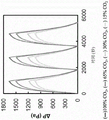
fig. 8A to 8C illustrate CO by a gas separation process according to one or more embodiments2Graphical representation of the results of the capture and release experiments;
fig. 9 illustrates CO through a gas separation process in accordance with one or more embodiments2Graphical representation of the results of the capture and release experiments; and
FIG. 10 illustrates CO by a gas separation process in accordance with one or more embodiments2Graphical representation of the results of the capture and release experiments.
Other aspects, embodiments and features of the present invention will become apparent from the following detailed description when considered in conjunction with the accompanying drawings. The figures are schematic and are not intended to be drawn to scale. For purposes of clarity, not every component may be labeled in every drawing, nor may every component of every embodiment of the invention be shown where illustration is not necessary to allow those of ordinary skill in the art to understand the invention. All patent applications and patents incorporated by reference herein are incorporated by reference in their entirety. In case of conflict, the present specification, including definitions, will control.
Detailed Description
The present disclosure relates generally to methods and systems for separating a target species (e.g., CO) from a gas mixture (e.g., a gas stream) by an electrochemical process2) An apparatus, system, and method.
According to some embodiments, an electrochemical swing (swing) process is used to provide gas separation. The electrochemical oscillation process can be carried out along one edge under one potentialA process of direction driving and reverse driving at different potentials. This can be achieved using redox active species that can be activated at one potential and deactivated at a different potential. In electrochemical swing separation, a redox active species may have a higher affinity for an elate (or adsorbate), such as a target species, in the activated state than in the deactivated state. According to such embodiments, energy is efficiently transferred to affect capture of a target species (e.g., CO)2) The electrochemical reaction of (1). In some embodiments, the applied electrochemical rocking process relies on adjusting the oxidation state of the electroactive species by applying a potential difference across the electrochemical cell, where a redox half-reaction occurs at the electrodes. This change in oxidation state of the electrolyte species at the electrodes and its subsequent migration in the electrolyte causes or is a result of the movement of electrons in the external circuit.
In some embodiments, an electrochemical cell is provided to perform a separation process. The electrochemical cell may comprise an electroactive material that selectively binds to CO when in its reduced form2Or other target substance. In some embodiments, the components of the electrochemical cell may be arranged in a manner that maximizes the electroactive surface area exposed to the gas.
In accordance with one or more embodiments, a method of separating a target species (e.g., carbon dioxide) from a gas mixture or stream using an electrochemical cell is described. The affinity of the electroactive species of the negative electrode to the target chemical species may be altered by changing the oxidation state of the electroactive species. In this way, the electroactive species may be utilized to capture and release the target chemical species. The redox species or electroactive species in the positive electrode can serve as an electron source and electron trap (electron sink) for reducing and oxidizing, respectively, the negative electroactive material.
Electrochemical cells for such processes are generally described, according to one or more embodiments. In some embodiments, an electrochemical cell may include a negative electrode and a positive electrode. In some embodiments, an electrochemical cell may include a first negative electrode and a second negative electrode, and a positive electrode positioned between the negative electrodes.
According to some embodiments, the one or more negative electrodes may include a gas permeable layer (also referred to as a substrate layer) and an electroactive composite layer (also referred to herein as a primary electroactive composite layer). In an electrochemical cell comprising two negative electrodes, the materials and components of each electrode may be the same or different.
The positive electrode may accordingly include an electroactive composite layer facing the first negative electrode and a second electroactive composite layer facing the second negative electrode. The electroactive composite layer of the positive electrode can also be referred to as a complementary electroactive composite layer because the electroactive species therein serves as an electron trap or source of electrons for the electroactive material of the negative electrode.
The electrochemical cell may further include a separator between each negative electrode and the positive electrode. Each of the first and second spacers can be saturated with a conductive liquid (e.g., an ionic liquid) such that the conductive liquid (e.g., the ionic liquid) is present in the spacers when the device is operated.
The primary electroactive composite layer includes a first electroactive species capable of interacting with a target species gas (e.g., CO) when the first electroactive species is in a reduced state2) Binding, and capable of releasing the target species gas when the first electroactive species is in an oxidized state. The electroactive species may be selected such that it has a strong affinity, when in the reduced state, for the intended target species for the intended particular application. For example, in which CO2In some embodiments where the target species is a selected electroactive species, the binding constant of the electroactive species to carbon dioxide can be 101M-1To 103M-1. In some embodiments, the binding constant of the selected electroactive species to a different target species may be 101M-1To 103M-1. Anthraquinones, such as the polymeric forms of the polyanthraquinones discussed further herein, are electroactive species that can be used. In some embodiments, in CO2In the presence of anthraquinone, is reduced to its dianion in a single step, then with CO2Binding to form a complex. It is also possible to use a catalyst which, after reduction, will react with CO2Other electroactive species that form covalent bonds to form carboxylate moieties. Further examples of such electroactive species include thiolates and bipyridines.
The term polyanthraquinone as used herein generally refers to any isomer of polyanthraquinone. Examples of the isomers of the polyanthraquinone that can be used as the electroactive substance include poly (1, 4-anthraquinone) (P14AQ) represented by the formula (I):

other possible isomers include: poly (1, 5-anthraquinone) (P15AQ), poly (1, 8-anthraquinone) (P18AQ) and poly (2, 6-anthraquinone) (P26 AQ). Other isomers are also possible.
The electroactive composite layer of the negative electrode may comprise carbonaceous material in addition to the electroactive species. Examples of suitable materials include carbon nanotubes (e.g., single-walled carbon nanotubes, multi-walled carbon nanotubes), carbon black, ketjen black (ketjen black), carbon black Super P, or graphene.
Because of the solubility of the isomer P14AQ in chloroform or other solvents, the isomer P14AQ is selected to be incorporated into the composite layer, which allows for better dispersion of the carbonaceous material in solution, according to some embodiments.
In some embodiments, the electroactive chemical can be immobilized to the negative electrode. Such embodiments may be distinguished from embodiments of other systems in which electroactive chemicals are transported from one electrode to another by convection. In some embodiments, the electroactive composite layer comprises an immobilized polymer composite that is an immobilized polymer composite of an electroactive species and a carbon-containing material. For example, in some embodiments, the electroactive composite layer comprises a polyanthraquinone (pAQ) -Carbon Nanotube (CNT) composite.
According to one or more embodiments, the electroactive composite layer of the negative electrode may have a particular weight ratio of electroactive material to carbonaceous material. The weight ratio may be selected to facilitate high current per mass of electroactive material. In some embodiments, the weight ratio of the mass of electroactive material to the mass of carbonaceous material may be from about 1: 1 to about 1: 10. In some embodiments, it may be about 1: 3. Other weight ratios are also possible.
The negative electrode may further include a gas permeable layer. The gas permeable layer (which may also be referred to as a substrate layer) may be proximate to the electroactive composite layer and face outward from the electrochemical cell. The gas stream may diffuse through the gas permeable layer to contact the electroactive composite layer. The gas permeable layer may contain a conductive material and act as a current collector within the cell.
The gas permeable layer may comprise a porous material. In some embodiments, the porosity of the layer may be, for example, about 70% to 90%. Other porosities are also possible. Examples of suitable materials for the air-permeable layer include, without limitation, carbon paper (treated, TEFLON-treated, or untreated), carbon cloth, and non-woven carbon mats. Other materials may also be used.
Turning to the positive electrode, in some embodiments, the positive electrode can include an electroactive layer (sometimes referred to as a complementary electroactive layer). The complementary electroactive layer may comprise a second electroactive species. In operation, the second electroactive species may serve as an electron source for reducing the first electroactive species present in the negative electrode. Likewise, the second electroactive species may act as an electron trap during oxidation of the first electroactive species. In this manner, the electroactive layers of the positive electrode can be described as "complementary". The second electroactive species may comprise, for example, polyvinylferrocene. The second electroactive species may comprise, for example, poly (3- (4-fluorophenyl) thiophene), or other faradaic redox species having a reduction potential at least 0.5 volts more positive than the first reduction potential of the first electroactive species (e.g., anthraquinone).
As with the primary electroactive composite layer of the negative electrode, the complementary electroactive composite layer of the positive electrode may comprise an immobilized polymer composite of an electroactive species and a carbonaceous material. Examples of carbonaceous materials include carbon nanotubes (e.g., single-walled carbon nanotubes, multi-walled carbon nanotubes), carbon black, ketjen black, carbon black Super P, or graphene. Other materials are also possible.
According to one or more embodiments, the electroactive composite layer of the positive electrode can have a particular weight ratio of electroactive material to carbonaceous material. The weight ratio may be selected to facilitate high current per mass of electroactive material. In some embodiments, the weight ratio of the mass of electroactive material to the mass of carbonaceous material may be from about 1: 2 to about 2: 1. In some embodiments, it may be about 1: 1. Other weight ratios are also possible.
In embodiments of an electrochemical cell in which the positive electrode has negative electrodes on either side, the positive electrode may include two electroactive composite layers each facing one negative electrode.
The positive electrode may also include a substrate layer adjacent to or between one or more electroactive composite layers. The base layer of the positive electrode may comprise the same or different material as the base layer of the negative electrode. For example, the base layer may comprise a material such as carbon paper (treated, TEFLON treated, or untreated), carbon cloth, or a non-woven carbon mat. Other materials are also possible. The base layer of the positive electrode may contain a conductive material and serve as a current collector within the cell.
A separator may be positioned between the positive electrode and each negative electrode. The separator may act as a protective layer to separate the different electrodes from each other and/or from other components in the electrochemical cell. The separator may comprise a porous structure. The material for the spacer may include, for example, a cellulose film, a polymer material, or a polymer-ceramic composite. Additional examples of spacers include PVDF spacers, PVDF-alumina spacers, or Celgard.
In some embodiments, an electrochemical cell may be provided with one or more separators saturated in a conductive liquid (e.g., an ionic liquid). In some embodiments, the electrochemical cell may be provided without an electrically conductive liquid in the separator, but with a separator that is capable of being saturated with an electrically conductive liquid when it is put into operation to perform a gas separation process. In some embodiments, the conductive liquid may comprise a metal oxideA subpluid, such as a room temperature ionic liquid ("RTIL"). The RTIL electrolyte may have low volatility (i.e., room temperature vapor pressure less than 10 a)-5Pa, e.g. 10-10Pa to 10-5Pa) to reduce the risk of drying of the electrode and to allow gas to flow past the electrode without significant evaporation or entrainment losses. The room temperature ionic liquid may comprise, for example, 1-butyl-3-methylimidazolium tetrafluoroborate ("Bmim BF) represented by the following formula (II)4”):

The ionic liquid may comprise an anionic component and a cationic component. The anion of the ionic liquid may include, without limitation: halide, sulfate, sulfonate, carbonate, bicarbonate, phosphate, nitrate, acetate, PF6-, BF4-, triflate, perfluorobutylsulfonate, bis (trifluoromethanesulfonyl) amide, trifluoroacetate, heptafluorobutyrate, haloaluminate, triazolamine (triazolide), and amino acid derivatives (e.g., proline with a proton on nitrogen removed). The cations of the ionic liquid may include, without limitation: imidazole, pyridine, pyrrole, phosphorus, ammonium, sulfur, thiazole, pyrazole, piperidine, triazole, pyrazole, oxazole, guanidine and dialkyl morpholine. In some embodiments, the conductive liquid may comprise a low volatility electrolyte solution.
An example of an electrochemical cell having one or more of the above-described components according to one or more embodiments is shown in fig. 1. Electrochemical cell 100 includes a positive electrode 120 positioned between two negative electrodes 110. Separator 130 separates positive electrode 120 from negative electrode 110. Each negative electrode 110 includes a gas permeable layer 112 away from the center of the cell 100 and a primary electroactive composite layer 114 facing the positive electrode 120. The positive electrode 120 includes a substrate layer 122 and two complementary electroactive composite layers 124 deposited thereon. The different components of electrochemical cell 100 may have certain characteristics described throughout this disclosure, for example, including the electrode materials described above. The configuration of two outwardly facing negative electrodes 110, such as shown in fig. 1, may provide the advantage of doubling the gas adsorption area exposed to the gas.
In accordance with one or more embodiments, the electrochemical cells generally described herein may be operated to perform a gas separation process. The process may include: applying a potential difference across the electrochemical cell, and will contain the target species (e.g. CO)2) Is introduced into the electrochemical cell to bind the target species to the first electroactive species, producing a treated gas stream.
According to one or more embodiments, the target species may comprise a nucleophilic molecule. According to one or more embodiments, the target species may comprise an aprotic acidic gas. According to one or more embodiments, the target substance may comprise a gas capable of forming a complex with pAQ or other electroactive material of the negative electrode. According to one or more embodiments, the target species may comprise carbon dioxide (CO)2). According to one or more embodiments, the target substance may comprise sulfur dioxide (SO)2). According to one or more embodiments, the target species may comprise a borane (BR3), wherein each R may be the same or different and is a suitable substituent (e.g., hydrogen, alkyl, aryl, etc., each optionally substituted). In some embodiments, the target substance may comprise one substance. In some embodiments, the target species may comprise more than one species. The potential window over which capture and release occur may depend on the particular target species of the embodiment, and thus, the enrichment and dissolution of the target species may be controlled by applying an appropriate potential difference across the electrochemical cell.
According to some embodiments, applying a positive voltage to the electrochemical cell during the charging mode causes a redox half-reaction at the negative electrode, wherein the electroactive species is reduced. As discussed, here, the electroactive species of the negative electrode is selected to be reactive to a target species (e.g., CO) when it is in a reduced state2) Has improved affinity property. By reducing the electroactive species and passing the gas stream over the surface of the negative electrode, the target species (e.g., CO)2) Can be bound to an electroactive species. In this way, canThe target species is removed from the gas stream to provide a treated gas stream.
According to some embodiments, wherein the electroactive species of the negative electrode is anthraquinone, the electroactive species may be reduced according to reaction (1) below:

according to some embodiments, wherein the electroactive species is reduced in the presence of a target species comprising carbon dioxide, the following reaction (2) may occur:

according to some embodiments, when the first electroactive species (e.g., polyanthraquinone) is reduced at the negative electrode, the second electroactive species (e.g., polyvinylferrocene) is oxidized at the positive electrode. During the charging mode, oxidation of the second electroactive species provides an electron source for driving reduction of the first electroactive species.
According to some embodiments, wherein the electroactive species of the positive electrode comprises polyvinylferrocene, the second electroactive species may be oxidized according to reaction (3) below:

although each of reactions (1) to (3) is shown as occurring in one direction, some reversibility may also be exhibited. Similar reactions can occur using different substances, as understood by one of ordinary skill in the art.
According to one or more embodiments, upon charging the electrochemical cell by applying a potential difference across the positive electrode and the negative electrode, electrons flow from a ferrocene (Fc) cell in the PVF-CNT composite on the positive electrode to the negative electrode through an external circuit, thereby oxidizing the ferrocene to ferrocene (Fc)+) (as shown in reaction (3)). At the negative electrode, CO of the anthraquinone unit in the pAQ-CNT composite diffuses to the negative electrode2Is reduced to the dianionic form p (AQ)2-). Divalent anions readily covalently bond with CO2Binding, as shown in formula (2), forms a complex p (AQ. [ CO ]2]2-)。
During the charging mode, the potential difference across the electrochemical cell may have a particular voltage. For example, in some embodiments, the potential difference can be at least 0V, at least 0.5V, at least 1.0V, or at least 1.5V. In some embodiments, the potential difference may be less than or equal to 2.0V, less than or equal to 1.5V, less than or equal to 1.0V, or less than or equal to 0.5V. Combinations of these voltages are also possible, for example, at least 0.5V and less than or equal to 2.0V. Other values are also possible.
Fig. 2A shows an exploded view of an exemplary electrochemical cell 100a operating in a charging mode according to one or more embodiments. The components of electrochemical cell 100a may be similar to those described herein with respect to electrochemical cell 100 described with respect to fig. 1. In fig. 2A, a power supply 140a and wiring 150a are used to apply a potential difference across electrochemical cell 100 a. This causes an electron flow 160a in the external circuit 150a, and the electron flow 160a guides the electrons to the main electrically active composite layer 114a of each negative electrode 110 a. A redox half-cell reaction occurs at the electroactive composite layer 114a to reduce the electroactive species immobilized in the layer 114 a. In its reduced state, the electroactive species exhibits an increased affinity for a target species (not shown) in the gas stream. The target species of the gas stream may permeate through the gas permeable layer 112A of the negative electrode, binding with the reduced material of the composite layer 114A.
Meanwhile, during operation in the charging mode, the positive electrode 120a serves as an electron source. A corresponding redox half-cell reaction occurs at the complementary electroactive composite layer 124a of the positive electrode 120a to oxidize its electroactive species. The oxidation reaction releases electrons from the complementary electroactive species. These electronic reaction products may then pass through the base layer 122a and/or the external wiring 150a to complete the circuit. The separator 130a separates the positive electrode 120a from the negative electrode 110 a.
In accordance with one or more embodiments, the operation of the electrochemical cell may further comprise applying a second potential difference across the electrochemical cell to release the target species from the first electroactive species, producing a target species-enriched gas stream. According to some embodiments, after operating the electrochemical cell in the charging mode for a period of time (during which the target species binds to the electroactive material of the negative electrode), operation may be switched to the discharging mode. During operation in the discharge mode, the applied voltage is switched to provide a flow of electrons in a direction opposite to the flow of electrons during the charge mode. When operating in a discharge mode, a negative voltage may be applied across the electrochemical cell. In the discharge mode, a redox half-reaction occurs at the negative electrode, wherein the electroactive species of the negative electrode is oxidized. During operation in the discharge mode, the target substance may be released from the material in the negative electrode to which it has been bound.
According to some embodiments, wherein the electroactive species of the negative electrode is anthraquinone, during the discharge mode, the electroactive species may be oxidized according to reaction (4) below:

according to some embodiments in which the electroactive activation species is oxidized after binding to the target species comprising carbon dioxide, the following reaction (5) may occur:

according to some embodiments, when the first electroactive species (e.g., polyanthraquinone) is oxidized at the negative electrode, the second electroactive species (e.g., polyvinylferrocene) is reduced at the positive electrode. During the discharge mode, the reduction of the second electroactive species acts as an electron trap.
According to some embodiments, wherein the electroactive species of the positive electrode comprises polyvinylferrocene, the second electroactive species may be reduced according to reaction (6) below:

although each of reactions (4) to (6) is shown as occurring in one direction, some reversibility may also be exhibited. Similar reactions can occur using different substances, as understood by one of ordinary skill in the art.
According to such embodiments, when the polarization of the external circuit is changed to allow electrons to flow in the opposite direction, the electroactive material of the negative electrode is oxidized by discharging the electrochemical cell. pAQ and CO2The covalent bond formed between the molecules is broken (as shown in reaction (5)), releasing CO2Gas and electrons, CO2Gas diffuses out of the negative electrode and electrons flow to the positive electrode to mix Fc+The unit is reduced to Fc (as shown in reaction (6)). According to such embodiments, pVF may be used as an electron source for reducing p (AQ) or for oxidizing p (AQ) [ CO ]2]2 -) The electron trap of (1).
During the discharge mode, the potential difference across the electrochemical cell may have a particular voltage. For example, in some embodiments, the potential difference may be less than 0V, less than or equal to-0.5V, less than or equal to-1.0V, or less than or equal to-1.5V. In some embodiments, the potential difference may be at least-2.0V, at least-1.5V, at least-1.0V, or at least-0.5V. Combinations of these voltages are also possible, for example, at least-2.0V and less than or equal to-0.5V. Other values are also possible.
Fig. 2B shows an exploded view of an exemplary electrochemical cell 100B operating in a discharge mode according to one or more embodiments. The components of electrochemical cell 100b are the same as the components of cell 100a of fig. 2A. However, the voltage applied by the power supply 140b has been changed to generate a potential difference that reverses the direction of the electron flow 160b through the external wiring 150 b. In the discharge mode, a redox half-cell reaction occurs at the electroactive composite layer 114b of the negative electrode 110b to oxidize the electroactive species immobilized in the layer 114 b. In its oxidized state, the electroactive species exhibits reduced affinity for the target species, resulting in release of the target species from the electroactive species. The released target species exits through the gas permeable layer 112b and may be directed for further processing, sequestration (or other desired purposes).
Meanwhile, the positive electrode 120b serves as an electron trap during operation in the discharge mode. A half-cell reaction occurs at the complementary electroactive composite layer 124b of the positive electrode 120b to reduce the electroactive species. During the reduction reaction, electrons traveling through the wiring 150b and the base layer 122b are bound to complementary electroactive species, thereby completing a circuit. The separator 130b separates the positive electrode 120b from the negative electrode 110 b.
Fig. 3 shows a schematic diagram of an exemplary electrochemical cell 300 according to one or more embodiments. Electrochemical cell 300 includes a negative electrode 310, a positive electrode 330, and a separator 320 therebetween. Fig. 3 also shows a second negative electrode 310 as an optional opposing first negative electrode 310 and second separator 320. The negative electrode 310 contains a first electroactive species that is reactive to a target species (e.g., CO) when in a reduced state2) Exhibit relatively increased affinity and are directed to a target species (e.g., CO) when in an oxidized state2) Exhibit a relatively reduced affinity. The positive electrode 320 contains different electroactive species. During operation in either the charge or discharge mode, a potential difference may be applied across electrochemical cell 300 to cause complementary redox reactions to occur at each electrode 310 and 320, as discussed elsewhere herein.
According to one or more embodiments, one or more electrochemical cells as described herein may be incorporated into a gas separation system. The gas separation system may comprise a plurality of electrochemical cells according to any embodiment described herein in fluid communication with a gas inlet and a gas outlet.
The gas separation system may include an external circuit connecting the first and second porous negative electrodes and the positive electrode of each electrochemical cell to a power source configured to apply a potential difference across the first and second negative electrodes and the positive electrode of each electrochemical cell.
Fig. 4 illustrates a schematic diagram of an exemplary gas separation system 400 in accordance with one or more embodiments. The system 400 includes a housing 460 having an inlet 470 and an outlet 480. Located within the housing is an electrochemical cell 405. Although only one battery 405 is shown in fig. 4 for clarity, one of ordinary skill in the art will readily appreciate that a plurality of batteries 405 may be located in the housing 460. A power source 440, which may be internal or external to housing 460, is connected to battery 405. The negative electrode 410 is connected to the power source 440 through a wiring 450a, and the positive electrode is connected through a wiring 450 b. When a voltage is applied to operate the battery in a charging mode (as described elsewhere herein), a flow of gas to be treated is delivered through inlet 470. The gas stream contains a target species intended to be at least partially removed by the system 400. The gas stream then travels close to the cell 405, in particular close to the negative electrode 410. The reduced electronegative material in the negative electrode 410 binds with the target species, thereby removing the target species from the target stream. Optional second negative electrode 410, second separator 420, and corresponding wiring 450a are shown in dashed lines. Although the embodiments shown in fig. 4 and others include an optional housing, it is understood that the electrochemical cells may be located in various environments, such as in series in a conduit, or without a housing in other instances.
Fig. 5 shows a schematic diagram of an exemplary system for performing a gas separation process during a charging mode in accordance with one or more embodiments. In fig. 5, a potential difference is applied across each electrochemical cell such that each electrochemical cell operates in a charging mode. In the charging mode, a redox reaction (e.g., reduction) of the electroactive species in the negative electrode 510 increases the affinity between the electroactive species and the target species 590. A gas stream 575 containing the target species 590 is introduced into the system and travels near the negative electrode 510. The increased affinity results in a target species (e.g., CO)2) Is bound to the electroactive material. In this manner, at least a portion of the target species is separated from the gas stream 575 to produce a treated gas stream 585.
The system 400 shown in fig. 4 may also be operated in a discharge mode by varying the voltage applied by the power source 440 to cause a flow of electrons in a direction opposite to the flow in the charge mode. This change results in a different redox reaction at the negative electrode 410, e.g., a reaction in which the electroactive material of the negative electrode is oxidized. This change in the oxidation state of the electroactive material causes the target species to be released from the electroactive material, producing a gas stream enriched in the target species. The gas stream enriched in the target species may exit through outlet 480 or an alternative outlet (not shown).
Since operation in the discharge mode results in the target species being released, the simultaneous introduction of the gas stream to be treated through inlet 470 will have the opposite effect. Thus, during operation in the discharge mode, the inlet 470 is closed or a different flow (e.g., waste flow) is redirected to the inlet.
According to one or more embodiments, a gas separation system may include a first set of electrochemical cells and a second set of electrochemical cells. Each of the first and second sets may include one or more electrochemical cells as described throughout this disclosure. The first and second sets may be arranged to run in parallel in an alternating manner such that one set of cells operates in a charging mode and captures a target species (e.g., CO) from a gas mixture2) While the other set of cells operates in a discharge mode and releases the target substance (e.g., CO)2). The system may include a separate housing for each set of electrochemical cells. The system may further comprise conduits and valves arranged to direct the flow in a desired manner. The gas separation system may allow for continuous or semi-continuous separation of a gas stream, wherein the gas stream is directed at a given moment to one set of cells operating in charge/capture mode while a separate target-rich stream is produced by another set of cells operating in discharge/release mode. Further, additional sets of electrochemical cells may be added in parallel or in series, as desired for the application.
An example of one embodiment of such a gas separation system is shown in fig. 6. In the gas separation system 600, a first set of electrochemical cells 605a is located in a first housing 660a and a second set of electrochemical cells 605b is located in a second housing 660 b. A conduit connects the gas inlet 670 to the housing inlets 672a and 672 b. The valve 684 may be arranged to direct flow to either of the groups 605a and 605b, depending on which group is currently operating in the charging mode.
In operation, a target species (e.g., CO) may be contained via inlet 6702) Is introduced into the gas separation system 600. When the first set of cells 605a is operating in the charge/capture mode, the valve 684 may be arranged to direct the flow proximate to the first set of cells 605a, wherein the target species may bind to the electroactive material in the cells 605a to produce a treated gas stream (a gas stream having a reduced concentration of the target species) that then exits the housing 660a through the outlet 673 a. A further valve 686a downstream of the housing outlet 673a may be arranged to direct a flow of treated gas through the treated gas outlet 680.
While the first set of cells 605a operates in a charging mode, the second set of cells 605b may operate in a discharging mode, wherein previously accumulated target species are released from the electroactive material of the second set of cells 605 b. In the embodiment shown, the valve 684 is arranged to isolate the gas treatment stream from the battery 605b operating in the discharge mode. The target substance is released from the battery 605b, creating a gas stream enriched in the target substance, and then exits the housing 660b through outlet 673 b. The valve 686b may be arranged to separate the target-rich stream from the treated stream outlet 680 and direct the target-rich stream to a waste outlet 682b, which in turn may be subjected to further processing, storage, etc.
After operating for a period of time in the manner described above, the mode of the batteries 605a and 605b may be reversed. The first set of cells 605b is then operated in a discharge mode to release the accumulated target species from its electrodes. During this time, the valve 684 is rearranged to isolate the process stream from the first set of cells 605 a. During this time, valve 686a is rearranged to direct the target-rich stream to waste outlet 682 a.
At the same time, the operation of the second set of cells 605b is reversed such that they operate in a charging mode to trap the target species and produce a treated stream. The inlet valve 684 is arranged to direct process flow from the system inlet 670 through a conduit to the second set of cells 605b via the second housing inlet 672 b. The outlet valve 686b is rearranged to direct the treated flow to the outlet 680.
In this manner, different sets of cells 605a and 605b may be cycled through mode while together providing continuous or semi-continuous processing of a gas stream containing a target species. While the particular embodiment shown in fig. 6 illustrates one particular arrangement of system components (e.g., valves, conduits, inlets and outlets), one of ordinary skill in the art will appreciate that different configurations may be provided to still meet the goal of providing continuous operation of the separated treated stream and the target species-enriched stream.
Fig. 7A shows a schematic diagram of an exemplary system for performing a gas separation process similar to the system of fig. 6, wherein a first set of cells 705a operates in a charging mode and a second set of cells 705b operates in a discharging mode, in accordance with one or more embodiments. In the charging mode, the applied voltage causes a redox reaction (e.g., reduction) of the electroactive species in the negative electrode 710a, increasing the affinity between the electroactive species and the target species 790. A gas stream 575 containing the target species 590 is introduced into the stack 705a and travels near the negative electrode 510 a. The increased affinity results in a target species (e.g., CO)2)790 to an electroactive material. In this manner, at least a portion of the target species is separated from the gas stream 775 to produce a treated gas stream 785.
In the discharge mode, a second applied voltage that causes a flow of electrons in a direction opposite to the flow of electrons during the charge mode causes a second redox reaction (e.g., oxidation) of the electroactive species in the negative electrode 710b, reducing the affinity between the electroactive species and the target species 790. The released target substance 790 enters the target substance-enriched gas stream 787.
Fig. 7B shows a schematic diagram of an exemplary system for performing a gas separation process similar to the system of fig. 6, with the mode of operation shown and described with respect to fig. 7A reversed. In fig. 7B, the voltage applied across the first set of cells 705a has been changed and the cells 705a are operated in a discharge mode to release the stored target substance 790 from the negative electrode 710a, producing a target substance-enriched gas stream. At the same time, the voltage applied across the second set of batteries 705b has also been changed so that it operates in a charging mode. The target substance 790 of the treatment stream 775 binds to the negative electrode 710b to produce a treated stream 785.
The electrochemical cells, systems, and methods described herein can be implemented in a variety of applications. The number of cells or battery packs may be scaled as needed to meet the requirements of a particular application. In some embodiments, the systems and methods described herein can be used to remove industrial fumes and enclosed spaces (e.g., airtight buildings, automobile cabins (reducing the cost of heating the incoming air for ventilation), and submarine and space cabins (where CO is present)2Increased levels can be catastrophic)) CO removal2. In embodiments involving the power industry, they may be used to capture various concentrations of post-combustion carbon dioxide. In addition, they can be used to capture sulfur dioxide and other gases from flue gases. In embodiments involving the oil and gas industry, the disclosed systems and methods may be used to capture carbon dioxide and other gases from various processes and divert them to downstream compression and/or processing. The disclosed systems and methods may be applied to capture carbon dioxide from natural gas combustion used to heat greenhouses in warm and cold climates, and then transfer the captured dioxide to a greenhouse for plants for photosynthesis use, i.e., to supply plants.
In accordance with one or more embodiments, a gas stream or a process stream can be introduced into a gas separation system at a particular flow rate. In some embodiments, the flow rate is from 1 ml/min to 100 ml/min. In some embodiments, the flow rate is from 1 ml/min to 20 ml/min. Other flows are possible, allowing for scalability of the system.
According to one or more embodiments, the target species (e.g., CO) in the introduced gas stream2) May have a particular concentration. In some embodiments, the target species concentration may be from 10ppm to 500 pm. In some embodiments, the concentration may be 0.5% to 15% by volume. Higher concentrations are also possible.
In some embodiments, an electrochemical cell may have a specific cycle time-the period of time during which a primary charge mode and a primary discharge mode are performed. The cycle time may be 60 seconds to 3600 seconds or 300 seconds to 1800 seconds. Other cycle times are also possible.
In some embodiments, the electroactive composite layer of the negative electrode can have a surface for absorbing a target species (e.g., CO)2) Of the specific capacity of the battery. For example, in some embodiments, the absorption capacity of the electroactive composite layer may be 0.01 moles/m2To 0.1 mol/m2. In some embodiments, the absorption capacity of the electroactive composite layer may be 0.01 moles/m2To 0.03 mol/m2. Other absorption capacities are also possible.
In some embodiments, the electrochemical cell can be operated such that the electroactive composite layer of the negative electrode is capable of absorbing a target species (e.g., CO) at a particular rate2). For example, in some embodiments, the rate of absorption capacity of the electroactive composite layer can be 0.0001 moles/m2From second to 0.001 mol/m2In seconds. In some embodiments, the rate of absorption capacity of the electroactive composite layer can be 0.0001 moles/m2From second to 0.0005 mol/m2In seconds. Other rates of absorption capacity are also possible.
In some embodiments, the electroactive composite layer of the negative electrode may have a specific surface area exposed to the gas flow, e.g., 5cm2To 20cm2. Other values are also possible.
In some embodiments, the gas permeable layer of the negative electrode or the substrate layer of the positive electrode may have a particular porosity, for example, the porosity may be 60% to 90%. Other values are also possible.
According to some embodiments, the electrochemical cell and components thereof may have a particular thickness. In some embodiments, the thickness of the electrochemical cell may be 200 μm to 750 μm. In some embodiments, the thickness of the electroactive composite layer of the negative or positive electrode may be 10 μm to 200 μm. In some embodiments, the thickness of the negative or positive electrode may be 50 μm to 200 μm. Other values are also possible.
The term "electrochemical cell" as used herein refers to a device in which redox half-reactions occur at the negative and positive electrodes. The term "electrochemical cell" is intended to include devices that meet these criteria even though the performance characteristics of the cell may arguably be greater than the pseudocapacitance of faradaic, and thus may also be referred to as a type of capacitor.
As used herein, an electroactive species generally refers to an agent (e.g., a chemical entity) that undergoes oxidation or reduction when exposed to a potential in an electrochemical cell.
In some embodiments, an electrode comprising a porous material is used. The porous electrode may be made of any suitable material and/or may include any suitable shape or size. In one non-limiting embodiment, the electrode comprises a porous carbonaceous material. The term carbonaceous material is given its ordinary meaning in the art and refers to an electrically conductive carbon-containing material or graphite. Non-limiting examples of carbonaceous materials include carbon nanotubes, carbon fibers (e.g., carbon nanofibers), and/or graphite. In such embodiments, the electrodes may be partially fabricated from a carbonaceous material or a carbonaceous material may be deposited on the underlying material. The underlying material typically comprises a conductive material, such as a metal. Other non-limiting examples of conductive materials are described herein.
In some embodiments, the electrode is porous. The porosity of an electrode may be measured as a percentage or fraction of the void space in the electrode. The percent porosity of the electrode can be measured using techniques known to those of ordinary skill in the art, such as using volume/density methods, water saturation methods, water evaporation methods, mercury intrusion porosimetry, and nitrogen adsorption methods. In some embodiments, the electrode may have a porosity of at least about 10%, a porosity of at least about 20%, a porosity of at least about 30%, a porosity of at least about 40%, a porosity of at least about 50%, a porosity of at least about 60%, a porosity of at least about 70% or greater. The pores may be open pores (e.g., pores having at least a portion open to the outer surface of the electrode and/or another pore). In some cases, only a portion of the electrode may be substantially porous. For example, in some cases, only a single surface of the electrode may be substantially porous. As another example, in some cases, the outer surface of the electrode may be substantially porous and the inner core of the electrode may be substantially non-porous. In a particular embodiment, the entire electrode is substantially porous.
The various components of the system, such as electrodes, power supplies, electrolytes, separators, containers, electrical circuits, insulating materials, etc., may be fabricated by one of ordinary skill in the art from any of the various components and components described in any of those patent applications described herein. The assembly may be molded, machined, extruded, pressed, isopressed (isopress), infiltrated, coated, or formed by any other suitable technique in the green or fired state. Techniques for forming components of the systems herein are readily known to those of ordinary skill in the art.
The electrodes may be of any size or shape. Non-limiting examples of shapes include sheets, cubes, cylinders, hollow tubes, spheres, and the like. The electrodes may be of any size. Additionally, the electrode may include means for connecting the electrode to another electrode, a power source, and/or another electrical device.
The various electrical components of the system may be electrically connected to at least one other electrical component by means for connecting. The means for connecting may be any material that allows electrical current to occur between the first component and the second component. A non-limiting example of a device for connecting two electrical components is a wire comprising a conductive material (e.g., copper, silver, etc.). In some cases, the system may also include an electrical connector between two or more components (e.g., wires and electrodes). In some cases, the wires, electrical connectors, or other means for connecting may be selected such that the resistance of the material is low. In some cases, the resistance may be significantly less than the resistance of the electrodes, electrolyte, and/or other components of the system.
In some embodiments, the power supply may supply a DC voltage to the system. Non-limiting examples include batteries, grids, regenerative power sources (e.g., wind generators, photovoltaic cells, tidal power generators), generators, and the like. The power source may include one or more of such power sources (e.g., batteries and photovoltaic cells).
In some embodiments, the system may include a separator, otherwise known as a septum. The diaphragm may be made of a suitable material such as a plastic film. Non-limiting examples of the included plastic film include polyamide, polyolefin resin, polyester resin, polyurethane resin, or acrylic resin containing lithium carbonate or potassium hydroxide or sodium-potassium peroxide dispersed therein.
The following examples are intended to illustrate certain embodiments of the invention, but do not exemplify the full scope of the invention.
Examples
Example 1
This example describes a non-limiting method for synthesizing poly (1, 4-anthraquinone) (P14AQ), which can be used as an electroactive material in the negative electrode of an electrochemical cell according to one or more embodiments described herein. A solution of 1.510g (5.45mmol) of dichloro-1, 4-anthraquinone in 20ml of Dimethylformamide (DMF) is added dropwise, with stirring at 65 ℃ under nitrogen, to a solution of 2.000g (7.27mmol) of bis (1, 5-cyclooctadiene) nickel (0), 1.134g (7.27mmol) of 2, 2' -bipyridine and 0.7ml (5.45mmol) of 1, 5-cyclooctadiene in 50ml of DMF. The mixture was allowed to react at 65 ℃ for 72 hours. After cooling to room temperature, 100ml of 1M hydrochloric acid (HCl) was added to the reaction mixture and stirred at room temperature for 1 hour. The mixture was then filtered and washed with 200ml 1M HCl, twice with 200ml deionized water, twice with 100ml DMF, then with 100ml water and with 100ml methanol. The residue was dried under vacuum for 24 hours. This procedure yielded 1.084g of polymer (96% yield).
Example 2
This example describes a non-limiting method for synthesizing a polymer-multiwalled carbon nanotube (MWCNT) composite comprising poly (1, 4-anthraquinone) (P14AQ), which can be used as the primary electroactive composite layer of an electrochemical cell according to one or more embodiments described herein. The composite was prepared by suspending 40mg of P14AQ (prepared according to the method described in example 1) and 120mg of MWCNT in 40ml of chloroform at 15 ℃The float was prepared by sonication for 40 minutes, resulting in a well dispersed ink. The ratio of P14AQ to CNT was optimized and the maximum current per mass of active material (polymer) was obtained when the weight ratio of P14AQ to CNT was 1: 3. The resulting composite exhibited a current increase of more than 30 times due to the higher surface area of the polymer exposed to the electrolyte compared to pure P14AQ, where the CNTs provided most of the conductivity through pi-pi interactions and produced a porous matrix modified by polymer chains for electrolyte penetration. Relative to Ag | AgNO3Reference electrode (which is at a first reduction potential E)1 0under-1.15V CO2Lower to a single quasi-reversible redox couple), P14AQ at N2Two reduction potentials at1 0-1.15V and
example 3
This example describes a non-limiting method for synthesizing a polymer-multiwall carbon nanotube (MWCNT) composite comprising Polyvinylferrocene (PVF) that can be used as a complementary electroactive composite layer for an electrochemical cell according to one or more embodiments described herein. The PVF-CNT composite was prepared by sonicating a suspension of 160mg PVF (available from polysciences, Inc.) and 160mg MWCNT in 40ml chloroform for 60 minutes at 15 ℃ to give a well-dispersed ink. This occurs in CO2Electrochemical window of about 1.2V, i.e., reduction potential of PVF (0.05V vs. Ag | AgNO)3) And a first reduction potential (-1.15V vs. Ag | AgNO) of P14AQ3). The optimum ratio by weight of the composite was found to be PVF: CNT 1: 1. The capacity balance of the electroactive layer composite for the negative and positive electrodes was done by weight charge calibration and determined as mAnode=1.12mCathode electrode。
Example 4
This example describes a non-limiting method for synthesizing an electrode of an electrochemical cell according to one or more embodiments described herein.
To form the electrode, a substrate material that can be used as a gas permeable layer for the negative electrode or a substrate layer for the positive electrode (e.g., Teflon-treated Toray carbon paper, untreated carbon paper, carbon cloth (available from ElectroChem Inc.), a non-woven carbon mat (available from Marktek, Inc.) was dip coated multiple times into a polymer-CNT ink (prepared as described in example 2 or example 3) to deposit a mass of composite material.
Example 5
This example describes a non-limiting method for manufacturing an electrochemical cell according to one or more embodiments described herein. An electrochemical cell was assembled by stacking the electrode substrate coated with P14AQ-CNT, the electrolyte separator, the electrode substrate coated with PVF-CNT, the electrolyte separator, the electrode substrate coated with P14 AQ-CNT. The electrolyte separator is 1-butyl-3-methylimidazolium tetrafluoroborate (BmimBF) in ionic liquid electrolyte4) Medium saturated Whatman cellulose filter paper, or Celgard 3501 saturated in ionic liquid electrolyte. Copper wire and conductive copper tape were used as current collectors.
Example 6
This example demonstrates the successful operation of an electrochemical cell formed according to the method described in the above example. Under atmospheric pressure filled with CO2The sealed chamber of (2) was tested by a chronoamperometric (constant potential difference) experiment and monitored for CO2Pressure changes due to trapping and releasing. Taking into account CO2Quasi-reversible nature of reductive addition to anthraquinone units, as compared to PVF anodes, by applying across the cell The potential difference of (2) realizes the reduction of P14AQ-CNT, and E is applied1 0< +0.5V, which is a large overpotential to back-drive the reaction, effects oxidation.
Reduced quinone with CO upon charging (negative charge) of the battery2Reaction, lowering the total pressure in the cell, while on discharge (positive charge), anthraquinone-CO2The compound is prepared from carbonic acid rootThe covalent bond in the molecule is broken and dissociated, and CO is regenerated2Molecular and anthraquinone units, restoring the original pressure in the chamber. Faraday efficiency from captured CO2The number of moles and the applied charge to calculate:

considering that the inner volume of the sealed chamber is 60cm3Faradaic efficiency was found to be 72% (highest). In addition, per mole of CO captured2The energy of (d) is calculated from the charge and the potential difference:
E=Qy
according to some embodiments, under optimal operating conditions, each mole of CO captured2The energy of (c) may be 30kJ to 70 kJ.
A potential difference is applied across the power supply path connected to the electrochemical cell and pressure sensors are used to monitor the pressure decrease and increase in the chamber at capture and release respectively. Pressure sensors were used to monitor the pressure decrease and increase in the chamber at capture and release, respectively. FIG. 8A shows CO at various concentrations2Three charge and discharge cycles of the electrochemical cell in the closed system below. FIG. 8B shows different concentrations of CO due to charging and discharging of the battery2Pressure fluctuations due to trapping and releasing of (2). FIG. 8C shows the temperature at 100% CO2Electrochemical charging and discharging superimposed on pressure fluctuations in a closed system. CO represented by pressure change of closed system2Absorption and release demonstrate that the electrochemical cell is operating for its intended use.
Example 7
This example demonstrates the successful operation of a flow-through system. Chronoamperometric experiments carried out in a closed system (example 6) were repeated in a flow system, in which the stack of assembled electrochemical cells was placed in a flow cell and brought to different concentrations of CO2N of (A)2And CO2Through the stack.
Using two negative (PAQ-CNT) electrodes and one Positive (PV)F-CNT) electrodes ten electrochemical cells were assembled. The surface area of each electrochemical cell exposed to the gas was 45cm2The total area of all stacks exposed to the gas was 450cm2. The PAQ-CNT electrode had a total loading of 500mg active material (375mg CNT and 125mg PAQ). The PVF-CNT electrode had a total loading of 600mg (300mg PVF and 300mg CNT). A stack of these cells spaced 2mm apart was placed in a gas flow cell (experimental setup) and gas was flowed through them. Study of 10ml/min and three CO2A mixture of nitrogen and carbon dioxide at inlet concentration. The bed volume of the system was 270cm3。
CO when the PAQ-CNT electrode is reduced, i.e., the battery is operated in charge mode2Is removed (captured) from the inlet stream (i.e., the gas treatment stream) and CO is detected in the outlet stream2The concentration is reduced. Treating a gas mixture of about 30 bed volumes, the bed being saturated and then releasing CO2. CO during oxidation, i.e. when the battery is operated in discharge mode2Is released into the same stream and CO is detected in the outlet stream2The concentration increased as shown in fig. 9. The sum of the total concentration decrease during capture equals the sum of the total concentration increase during release, which is 24ml CO2. Fig. 10 shows a breakthrough curve for the trapping part of the curve in fig. 9. As the inlet concentration increases, breakthrough is achieved at a smaller multiple of the bed volume. Based on the application, a threshold outlet concentration may be set, which once reached, the stack of cells is regenerated by applying an oxidation potential. In practice, a plurality of such stacks will be operated in parallel, with one or more stacks being CO-enriched2Capture of CO in the stream of2To produce CO lean2By passing the other stack of CO2Released into the purge stream or purge stream for regeneration.
While several embodiments of the invention have been described and illustrated herein, those of ordinary skill in the art will readily envision a variety of other means and/or structures for performing the function and/or obtaining the results and/or one or more of the advantages described herein, and each of such variations and/or modifications is deemed to be within the scope of the present invention. More generally, those skilled in the art will readily appreciate that all parameters, dimensions, materials, and/or configurations described herein are meant to be exemplary and that the actual parameters, dimensions, materials, and/or configurations will depend upon the specific application or applications for which the teachings of the present invention is/are used. Those skilled in the art will recognize, or be able to ascertain using no more than routine experimentation, many equivalents to the specific embodiments of the invention described herein. It is, therefore, to be understood that the foregoing embodiments are presented by way of example only and that, within the scope of the appended claims and equivalents thereto, the invention may be practiced otherwise than as specifically described and claimed. The present invention is directed to each individual feature, system, article, material, kit, and/or method described herein. In addition, any combination of two or more such features, systems, articles, materials, kits, and/or methods, if such features, systems, articles, materials, kits, and/or methods are not mutually inconsistent, is included within the scope of the present invention.
As used herein in the specification and in the claims, an indefinite article "a" or "an" should be understood to mean "at least one" unless explicitly stated to the contrary.
The phrase "and/or" as used herein in the specification and claims should be understood to mean "one or both" of the elements so connected, i.e., the elements may be present together in some cases and separately in other cases. Other elements may optionally be present in addition to the elements explicitly recited by the "and/or" clause, whether related or unrelated to those elements explicitly recited, unless explicitly stated to the contrary. Thus, as a non-limiting example, when used in conjunction with an open-ended language such as "comprising," the expression "a and/or B" may refer in one embodiment to the presence of a without B (optionally including elements other than B); in another embodiment, may refer to the presence of B without A (optionally including elements other than A); in another embodiment may refer to both a and B (optionally including other elements), and the like.
As used herein in the specification and claims, "or" is understood to have the same meaning as "and/or" as defined above. For example, when an item is listed in a list, "or" and/or "should be understood as being inclusive, i.e., including not only at least one of the number of elements or list of elements, but also more than one, and optionally including additional unlisted elements. Only terms explicitly indicating the opposite meaning, such as "only one" or "exactly one", or "consisting of … …" when used in the claims, will be referred to as including a plurality or exactly one of the list elements. In general, the term "or" as used herein should only be understood as an exclusive alternative (i.e., "one or the other, but not both") when followed by other exclusive terms such as "any," one, "" only one, "or" exactly one. "consisting essentially of … …" when used in the claims shall have the ordinary meaning as used in the patent law field.
As used herein in the specification and in the claims, when referring to a list of one or more elements, the phrase "at least one" should be understood to mean at least one element selected from any one or more of the elements in the list of elements, but not necessarily including each and every element explicitly listed in the list of elements, and not excluding any combinations of elements in the list of elements. The definition also allows that elements may optionally be present other than the elements specifically identified in the list of elements to which the phrase "at least one" refers, whether or not related to those elements specifically identified. Thus, as a non-limiting example, "at least one of a and B" (or, equivalently, "at least one of a or B," or, equivalently, "at least one of a and/or B") can refer in one embodiment to at least one a, optionally including more than one a, but not the presence of B (and optionally including elements other than B); in another embodiment, may refer to at least one B, optionally including more than one B, but no a (and optionally including elements other than a); in another embodiment, may refer to at least one a, optionally including more than one a, and at least one B, optionally including more than one B (and optionally including other elements), and the like.
In the claims, as well as in the foregoing specification, all transitional phrases (e.g., "including," "comprising," "carrying," "having," "containing," "involving," "holding," etc.) are to be understood to be open-ended, i.e., to mean including but not limited to. The transitional phrases "consisting of … …" and "consisting essentially of … …" should be closed or semi-closed transitional phrases, respectively, as described in the U.S. Patent Office Patent examination Manual of Patent application programs section 2111.03.
The invention also provides the following technical scheme:
note 1 that an electrochemical cell includes:
a first negative electrode and a second negative electrode each comprising a gas permeable layer and a main electroactive composite layer;
a positive electrode positioned between the first negative electrode and the second negative electrode and including a first complementary electroactive composite layer facing the first negative electrode and a second complementary electroactive composite layer facing the second negative electrode;
a first separator between the first negative electrode and the positive electrode; and
a second separator between the second negative electrode and the positive electrode, wherein each of the first separator and the second separator is capable of being saturated with an ionic liquid.
Note 8 the electrochemical cell of note 6, wherein the complementary electroactive composite layer comprises a second immobilized polymer composite that is the second immobilized polymer composite of a second electroactive species and a second carbon-containing material.
Note 9. the electrochemical cell according to note 8, wherein the second carbonaceous material is selected from the group consisting of carbon nanotubes, graphene, and carbon black.
Appendix 11. the electrochemical cell according to appendix 10, wherein the base layer comprises a material selected from the group consisting of carbon paper, carbon cloth, and a non-woven carbon mat.
Note 12 the electrochemical cell according to note 1, wherein each of the first separator and the second separator comprises one of a cellulose film, a polymer material, or a polymer-ceramic composite material.
Note 13. the electrochemical cell according to note 1, wherein each of the first separator and the second separator is saturated with a room-temperature ionic liquid.
Note 14. the electrochemical cell according to Note 1, wherein the room-temperature ionic liquid contains Bmim BF4。
Appendix 15. the electrochemical cell according to appendix 1, wherein the gas-permeable layer comprises a material selected from the group consisting of carbon paper, carbon cloth, and a non-woven carbon mat.
Note 16. the electrochemical cell according to note 1, wherein the porosity of the gas-permeable layer is 70% to 90%.
Note 17. the electrochemical cell of Note 1, further comprising an external circuit connecting the first and second negative electrodes and the positive electrode to a power source configured to apply a potential difference across the first and second negative electrodes and the positive electrode.
Reference numeral 18, a gas separation system, comprising:
a plurality of electrochemical cells in fluid communication with a gas inlet and a gas outlet, each of the plurality of electrochemical cells comprising:
a first porous negative electrode and a second porous negative electrode, each comprising a first electroactive species;
a positive electrode comprising a second electroactive species;
a first separator located between the first porous negative electrode and the positive electrode; and
a second separator between the second porous negative electrode and the positive electrode, wherein
Each of the first separator and the second separator is capable of being saturated with an ionic liquid.
Appendix 19. the gas separation system of appendix 18, wherein the first electroactive species is immobilized in a first polymer composite.
Appendix 21. the gas separation system of appendix 18, wherein the first electroactive species comprises a polyanthraquinone.
Appendix 22. the gas separation system of appendix 21, wherein the second electroactive species comprises polyvinylferrocene.
Appendix 23. the gas separation system of appendix 18, wherein each of the first separator and the second separator is saturated with a room temperature ionic liquid.
Note 24. the gas separation system of Note 23, where the room temperature ionic liquid comprises Bmim BF4。
Appendix 26. the gas separation system of appendix 18, further comprising an external circuit connecting the first and second porous negative electrodes and the positive electrode of each electrochemical cell to a power supply configured to apply a potential difference across the first and second negative electrodes and the positive electrode of each electrochemical cell.
Reference 27. a method of treating a gas stream, the method comprising:
applying a first potential difference across an electrochemical cell, the electrochemical cell comprising:
at least one porous negative electrode comprising a first electroactive species;
a positive electrode comprising a second electroactive species; and
a separator saturated with an electrically conductive liquid and located between the at least one porous negative electrode and the positive electrode; and
introducing a gas stream comprising a target species into the electrochemical cell to bind the target species to the first electroactive species to produce a treated gas stream.
Note 28. the method according to note 27, wherein the target substance contains CO2。
Note 29 the method according to note 27, wherein the first potential difference is 0.5V to 2.0V.
Supplementary note 31. the method according to supplementary note 30, wherein the second potential difference is-0.5V to-2.0V.
Appendix 32. the method of appendix 27, wherein the first electroactive species comprises a polyanthraquinone.
Appendix 33. the method of appendix 27, wherein the second electroactive species comprises polyvinylferrocene.
Appendix 34. the method of appendix 27, wherein the conductive liquid comprises a room temperature ionic liquid.
Reference numeral 36. a method of operating a gas separation system comprising a first set of electrochemical cells and a second set of electrochemical cells, the method comprising:
introducing a gas stream comprising a target species into the gas separation system;
operating the first set of electrochemical cells in a charging mode to bind the target species to a first electroactive species of the first set of electrochemical cells to produce a treated gas stream; and
simultaneously operating the second set of electrochemical cells in a discharge mode to release the target species from the first electroactive species of the second set of electrochemical cells to produce a target species-enriched gas stream;
wherein each electrochemical cell of the first set of electrochemical cells and the second set of electrochemical cells comprises:
at least one porous negative electrode comprising a first electroactive species;
a positive electrode comprising a second electroactive species; and
a separator saturated with ionic liquid and located between the at least one porous negative electrode and the positive electrode.
Note 37. the method according to note 36, wherein the target substance contains CO2。
Appendix 38. the method of appendix 36, wherein operating the first set of electrochemical cells in the charging mode includes applying a first potential difference of 0.0 to 2.0V across each electrochemical cell in the first set.
Appendix 39. the method of appendix 38, wherein operating the second set of electrochemical cells in the discharge mode includes applying a second potential difference of 0.0V to-2.0V across each electrochemical cell in the second set.
Appendix 41. the method of appendix 40, further comprising reversing the second potential difference to operate the second set of electrochemical cells in the charging mode.
Appendix 42. the method of appendix 36, wherein the first electroactive species comprises a polyanthraquinone.
Appendix 43. the method of appendix 36, wherein the second electroactive species comprises polyvinylferrocene.
Appendix 44. the method of appendix 36, wherein the conductive liquid comprises a room temperature ionic liquid.
Claims (10)
1. An electrochemical cell, comprising:
a first negative electrode and a second negative electrode each comprising a gas permeable layer and a main electroactive composite layer;
a positive electrode positioned between the first negative electrode and the second negative electrode and including a first complementary electroactive composite layer facing the first negative electrode and a second complementary electroactive composite layer facing the second negative electrode;
a first separator between the first negative electrode and the positive electrode; and
a second separator between the second negative electrode and the positive electrode, wherein each of the first separator and the second separator is capable of being saturated with an ionic liquid.
2. The electrochemical cell of claim 1, wherein the primary electrically active composite layer comprises a first electrically active substance capable of binding with carbon dioxide gas when the first electrically active substance is in a reduced state and releasing carbon dioxide gas when the first electrically active substance is in an oxidized state.
3. The electrochemical cell of claim 1, wherein the primary electroactive composite layer comprises a binding constant to carbon dioxide of 10 in a reduced state1M-1To 103M-1Of the first electroactive species of (a).
4. The electrochemical cell of claim 1, wherein the primary electroactive composite layer comprises a first electroactive species comprising a polyanthraquinone.
5. The electrochemical cell of claim 1, wherein the complementary electroactive composite layer comprises a second electroactive species comprising polyvinylferrocene.
6. The electrochemical cell of claim 1, wherein the primary electroactive composite layer comprises a first immobilized polymer composite that is the first immobilized polymer composite of a first electroactive species and a first carbon-containing material.
7. The electrochemical cell of claim 6, wherein the first carbonaceous material is selected from the group consisting of carbon nanotubes, graphene, and carbon black.
8. A gas separation system comprising:
a plurality of electrochemical cells in fluid communication with a gas inlet and a gas outlet, each of the plurality of electrochemical cells comprising:
a first porous negative electrode and a second porous negative electrode, each comprising a first electroactive species;
a positive electrode comprising a second electroactive species;
a first separator located between the first porous negative electrode and the positive electrode; and
a second separator located between the second porous negative electrode and the positive electrode, wherein each of the first separator and the second separator is capable of being saturated with an ionic liquid.
9. A method of treating a gas stream, the method comprising:
applying a first potential difference across an electrochemical cell, the electrochemical cell comprising:
at least one porous negative electrode comprising a first electroactive species;
a positive electrode comprising a second electroactive species; and
a separator saturated with an electrically conductive liquid and located between the at least one porous negative electrode and the positive electrode; and
introducing a gas stream comprising a target species into the electrochemical cell to bind the target species to the first electroactive species to produce a treated gas stream.
10. A method of operating a gas separation system comprising a first set of electrochemical cells and a second set of electrochemical cells, the method comprising:
introducing a gas stream comprising a target species into the gas separation system;
operating the first set of electrochemical cells in a charging mode to bind the target species to a first electroactive species of the first set of electrochemical cells to produce a treated gas stream; and
simultaneously operating the second set of electrochemical cells in a discharge mode to release the target species from the first electroactive species of the second set of electrochemical cells to produce a target species-enriched gas stream;
wherein each electrochemical cell of the first set of electrochemical cells and the second set of electrochemical cells comprises:
at least one porous negative electrode comprising a first electroactive species;
a positive electrode comprising a second electroactive species; and
a separator saturated with ionic liquid and located between the at least one porous negative electrode and the positive electrode.
Applications Claiming Priority (4)
| Application Number | Priority Date | Filing Date | Title |
|---|---|---|---|
| US201562246640P | 2015-10-27 | 2015-10-27 | |
| US62/246,640 | 2015-10-27 | ||
| PCT/US2016/058806 WO2017075014A1 (en) | 2015-10-27 | 2016-10-26 | Electrochemical process for gas separation |
| CN201680076165.4A CN108463433B (en) | 2015-10-27 | 2016-10-26 | Electrochemical process for gas separation |
Related Parent Applications (1)
| Application Number | Title | Priority Date | Filing Date |
|---|---|---|---|
| CN201680076165.4A Division CN108463433B (en) | 2015-10-27 | 2016-10-26 | Electrochemical process for gas separation |
Publications (1)
| Publication Number | Publication Date |
|---|---|
| CN114725317A true CN114725317A (en) | 2022-07-08 |
Family
ID=58562132
Family Applications (2)
| Application Number | Title | Priority Date | Filing Date |
|---|---|---|---|
| CN202210357090.4A Pending CN114725317A (en) | 2015-10-27 | 2016-10-26 | Electrochemical process for gas separation |
| CN201680076165.4A Active CN108463433B (en) | 2015-10-27 | 2016-10-26 | Electrochemical process for gas separation |
Family Applications After (1)
| Application Number | Title | Priority Date | Filing Date |
|---|---|---|---|
| CN201680076165.4A Active CN108463433B (en) | 2015-10-27 | 2016-10-26 | Electrochemical process for gas separation |
Country Status (6)
| Country | Link |
|---|---|
| US (4) | US10464018B2 (en) |
| EP (1) | EP3368474B1 (en) |
| JP (3) | JP7025765B2 (en) |
| KR (2) | KR20240035640A (en) |
| CN (2) | CN114725317A (en) |
| WO (1) | WO2017075014A1 (en) |
Families Citing this family (39)
| Publication number | Priority date | Publication date | Assignee | Title |
|---|---|---|---|---|
| JP7025765B2 (en) | 2015-10-27 | 2022-02-25 | マサチューセッツ インスティテュート オブ テクノロジー | Electrochemical process for gas separation |
| CA3033983A1 (en) * | 2016-08-16 | 2018-02-22 | Massachusetts Institute Of Technology | Removal of metal ions from aqueous solution via liquid/liquid extraction and electrochemistry |
| US10744457B2 (en) * | 2017-07-25 | 2020-08-18 | Hamilton Sundstrand Corporation | Electrochemical separator |
| US20190157012A1 (en) * | 2017-11-03 | 2019-05-23 | Battelle Memorial Institute | Compositions and methods for polarization-switched, solid-state molecular pumping |
| EP3735311A4 (en) * | 2018-01-05 | 2021-10-20 | President and Fellows of Harvard College | <sup2/><sub2/> 2 proton coupled electrochemical cocapture system |
| WO2020036676A1 (en) * | 2018-08-14 | 2020-02-20 | Massachusetts Institute Of Technology | Production of chemical products using electrochemical flow systems and slug flow and associated methods |
| US11603597B2 (en) | 2018-08-14 | 2023-03-14 | Massachusetts Institute Of Technology | Production of chemical products using electrochemical flow systems and mediators and associated methods |
| WO2021041732A1 (en) * | 2019-08-28 | 2021-03-04 | Massachusetts Institute Of Technology | Electrochemically mediated gas capture, including from low concentration streams |
| KR20220052984A (en) * | 2019-08-28 | 2022-04-28 | 메사추세츠 인스티튜트 오브 테크놀로지 | Electrochemically mediated gas capture, including gas capture from low concentration streams |
| US11598012B2 (en) * | 2019-08-28 | 2023-03-07 | Massachusetts Institute Of Technology | Electrochemically mediated gas capture, including from low concentration streams |
| WO2021041734A1 (en) * | 2019-08-28 | 2021-03-04 | Massachusetts Institute Of Technology | Electrochemical capture of lewis acid gases |
| US11872525B2 (en) | 2020-03-31 | 2024-01-16 | Massachusetts Institute Of Technology | Porous medium with adjustable fluid permeability and associated systems and methods |
| CN116018199A (en) * | 2020-06-11 | 2023-04-25 | 沃道克斯公司 | Electro-swing adsorption cell with patterned electrodes for separating gas components |
| WO2021253010A1 (en) * | 2020-06-12 | 2021-12-16 | Ramaco Carbon Llc | Systems and methods for processing coal for use in a direct air capture system |
| CN115803101A (en) * | 2020-07-20 | 2023-03-14 | 株式会社可乐丽 | Acid gas separation equipment, air purifier, air conditioner, and acid gas concentration device |
| JP2022025699A (en) * | 2020-07-29 | 2022-02-10 | 株式会社日立製作所 | Gas separator and gas system |
| JP7459755B2 (en) | 2020-10-20 | 2024-04-02 | 株式会社デンソー | Electrochemical Cells and Carbon Dioxide Capture Systems |
| CN112387089A (en) * | 2020-10-22 | 2021-02-23 | 李峰利 | Recycling device for carbon dioxide in industrial production waste gas |
| JP7453651B2 (en) | 2020-10-30 | 2024-03-21 | 株式会社デンソー | Electrochemical cells and carbon dioxide capture systems |
| CA3201416A1 (en) * | 2020-11-10 | 2022-05-19 | Verdox, Inc. | Composite for electrochemical gas separation |
| IL302765A (en) * | 2020-11-10 | 2023-07-01 | Verdox Inc | Quinone-containing poly(arylene), methods for the manufacture thereof, and use for electrochemical gas separation |
| WO2022104000A1 (en) * | 2020-11-13 | 2022-05-19 | Verdox, Inc. | Composite for electrochemical gas separation |
| JP2023551283A (en) * | 2020-11-30 | 2023-12-07 | アリゾナ・ボード・オブ・リージェンツ・オン・ビハーフ・オブ・アリゾナ・ステイト・ユニバーシティー | Apparatus and method for passive capture of atmospheric carbon dioxide using electric swing materials |
| US11857914B2 (en) * | 2020-12-08 | 2024-01-02 | University Of Kentucky Research Foundation | Electrochemical apparatus for acid gas removal and hydrogen generation |
| JP2022131439A (en) * | 2021-02-26 | 2022-09-07 | 株式会社デンソー | Carbon dioxide recovery system |
| WO2022185903A1 (en) * | 2021-03-04 | 2022-09-09 | 株式会社クラレ | Carbon dioxide adsorption battery and charge/discharge device |
| WO2022216355A1 (en) | 2021-04-07 | 2022-10-13 | Verdox, Inc. | Method for electrochemical gas separation |
| JP2022177883A (en) * | 2021-05-19 | 2022-12-02 | 株式会社デンソー | Carbon dioxide recovery system |
| US20230012689A1 (en) * | 2021-06-28 | 2023-01-19 | Verdox, Inc | Electroactive species and method for electrochemical gas separation |
| WO2023003029A1 (en) * | 2021-07-21 | 2023-01-26 | 千代田化工建設株式会社 | Carbon dioxide recovery system |
| JP2023044999A (en) * | 2021-09-21 | 2023-04-03 | 株式会社デンソー | Carbon dioxide recovery system |
| JP2023046605A (en) * | 2021-09-24 | 2023-04-05 | 株式会社デンソー | gas recovery system |
| JP2023046607A (en) * | 2021-09-24 | 2023-04-05 | 株式会社デンソー | gas recovery system |
| WO2023167138A1 (en) | 2022-03-04 | 2023-09-07 | 日本碍子株式会社 | Electrochemical element operation method |
| JPWO2023167139A1 (en) | 2022-03-04 | 2023-09-07 | ||
| JP2023161482A (en) | 2022-04-25 | 2023-11-07 | 株式会社デンソー | Carbon dioxide recovery system |
| JP2023161481A (en) | 2022-04-25 | 2023-11-07 | 株式会社デンソー | Carbon dioxide recovery system |
| JP2024010600A (en) * | 2022-07-12 | 2024-01-24 | 株式会社デンソー | Carbon dioxide recovery system |
| JP2024017801A (en) | 2022-07-28 | 2024-02-08 | 株式会社デンソー | Carbon dioxide recovery system |
Family Cites Families (60)
| Publication number | Priority date | Publication date | Assignee | Title |
|---|---|---|---|---|
| US3206333A (en) * | 1962-03-20 | 1965-09-14 | Prototech Inc | Electrochemical structure |
| US3540934A (en) * | 1967-07-11 | 1970-11-17 | Jan Boeke | Multiple cell redox battery |
| JPS63202858A (en) * | 1987-02-18 | 1988-08-22 | Matsushita Electric Ind Co Ltd | Nonaqueous electrolyte battery |
| BR8807357A (en) * | 1987-12-14 | 1990-05-22 | Hughes Aircraft Co | ELECTRODES APPLIANCE |
| US5770033A (en) | 1993-07-13 | 1998-06-23 | Lynntech, Inc. | Methods and apparatus for using gas and liquid phase cathodic depolarizers |
| US5776351A (en) * | 1994-04-20 | 1998-07-07 | Mcginness; Michael P. | Method for regeneration and closed loop recycling of contaminated cleaning solution |
| DE69923280D1 (en) * | 1998-11-30 | 2005-02-24 | Canon Kk | Process and apparatus for the decomposition of halogenated aliphatic and aromatic compounds |
| US6537514B1 (en) * | 1999-10-26 | 2003-03-25 | Praxair Technology, Inc. | Method and apparatus for producing carbon dioxide |
| JP3708426B2 (en) | 2000-11-13 | 2005-10-19 | Necトーキン株式会社 | Proton conducting polymer secondary battery |
| US6560471B1 (en) * | 2001-01-02 | 2003-05-06 | Therasense, Inc. | Analyte monitoring device and methods of use |
| US6712949B2 (en) * | 2001-07-22 | 2004-03-30 | The Electrosynthesis Company, Inc. | Electrochemical synthesis of hydrogen peroxide |
| AU2002367404A1 (en) * | 2001-12-28 | 2003-07-24 | University And Community College System Of Nevada On Behalf Of The University Of Nevada, Reno | Redox-switchable materials |
| AUPS172702A0 (en) | 2002-04-12 | 2002-05-23 | Commonwealth Scientific And Industrial Research Organisation | An electrochemical cell, a porous working electrode and a process for he conversion of a species from one oxidation state to another by the electrochemical oxidation or reduction thereof |
| TWI288495B (en) * | 2003-03-27 | 2007-10-11 | Nec Tokin Corp | Electrode and electrochemical cell therewith |
| RU2347608C2 (en) * | 2003-05-11 | 2009-02-27 | Бен-Гурион Юниверсити Оф Дзе Негев Рисерч Энд Дивелопмент Оторити | Incapsulated essential oils |
| US20040229117A1 (en) | 2003-05-14 | 2004-11-18 | Masaya Mitani | Electrochemical cell stack |
| JP2005100926A (en) * | 2003-05-14 | 2005-04-14 | Nec Tokin Corp | Electrochemical cell laminate |
| US7169497B2 (en) * | 2003-05-15 | 2007-01-30 | The Gillette Company | Electrochemical cells |
| FR2880823B1 (en) * | 2005-01-20 | 2008-02-22 | Total France Sa | HYDROTREATING CATALYST, PROCESS FOR PREPARING THE SAME AND USE THEREOF |
| GB0502227D0 (en) | 2005-02-03 | 2005-03-09 | Thermal Energy Systems Ltd | Gas separation and compresssion device |
| BRPI0612885B1 (en) * | 2005-06-30 | 2017-03-07 | Akzo Nobel Nv | process for the production of alkali metal chlorate |
| CN101243156A (en) * | 2005-08-15 | 2008-08-13 | 住友化学株式会社 | Metal complex-containing luminescent material and photoelectric device using the same |
| JP5147681B2 (en) * | 2006-03-01 | 2013-02-20 | 三菱電機株式会社 | Toxic gas treatment device and water treatment device |
| CN101828283B (en) * | 2007-08-21 | 2014-09-17 | A123系统股份有限公司 | Separator for electrochemical cell and method for its manufacture |
| US8900435B2 (en) * | 2007-12-19 | 2014-12-02 | Palo Alto Research Center Incorporated | Separating gas using ion exchange |
| JP2009217992A (en) * | 2008-03-07 | 2009-09-24 | Univ Waseda | Quinone polymer electrode, charge storage material and battery cell |
| WO2010143250A1 (en) | 2009-06-08 | 2010-12-16 | トヨタ自動車株式会社 | Fuel cell system |
| EP2548257B1 (en) * | 2010-03-18 | 2019-09-11 | Blacklight Power, Inc. | Electrochemical hydrogen-catalyst power system |
| US20130084474A1 (en) | 2010-03-18 | 2013-04-04 | Randell L. Mills | Electrochemical hydrogen-catalyst power system |
| US8500987B2 (en) | 2010-03-19 | 2013-08-06 | Liquid Light, Inc. | Purification of carbon dioxide from a mixture of gases |
| JP2012025601A (en) | 2010-07-21 | 2012-02-09 | Sharp Corp | Carbon dioxide separator and method for using the same |
| JP5484362B2 (en) | 2011-01-13 | 2014-05-07 | 日立建機株式会社 | Outside air introduction device for air conditioner for work equipment |
| WO2012145407A2 (en) | 2011-04-20 | 2012-10-26 | Lehigh University | Supercapacitive swing adsorption |
| JP5604588B2 (en) * | 2011-04-21 | 2014-10-08 | パナソニック株式会社 | Carbon dioxide adsorption and release device |
| WO2012164913A1 (en) * | 2011-05-31 | 2012-12-06 | パナソニック株式会社 | Carbon dioxide enrichment device |
| US20130045399A1 (en) * | 2011-08-16 | 2013-02-21 | Primus Power Corporation | Flow Battery with Reactant Separation |
| US9056275B2 (en) | 2011-08-18 | 2015-06-16 | Arizona Board Of Regents, A Body Corporate Of The State Of Arizona Acting For An On Behalf Of Arizona State University | Capture and release of carbon dioxide |
| US9567678B2 (en) * | 2011-08-29 | 2017-02-14 | Massachusetts Institute Of Technology | Methods and systems for carrying out a pH-influenced chemical and/or biological reaction |
| WO2013096220A1 (en) * | 2011-12-20 | 2013-06-27 | Applied Materials, Inc. | Apparatus and method for hot coating electrodes of lithium-ion batteries |
| US10329676B2 (en) | 2012-07-26 | 2019-06-25 | Avantium Knowledge Centre B.V. | Method and system for electrochemical reduction of carbon dioxide employing a gas diffusion electrode |
| DE102012016317A1 (en) | 2012-08-14 | 2014-02-20 | Jenabatteries GmbH | Redox flow cell for storing electrical energy |
| JP2014154225A (en) * | 2013-02-05 | 2014-08-25 | Sony Corp | Electrode material, electrode, and battery |
| GB2513103B (en) * | 2013-03-04 | 2016-12-21 | Schlumberger Holdings | Electrochemical flow reactors for hydrogen peroxide synthesis |
| US9777391B2 (en) * | 2013-05-08 | 2017-10-03 | Chiral Research, Inc. | Purification methods and systems for contaminated liquids and mineral slurries |
| JP2015036128A (en) * | 2013-08-12 | 2015-02-23 | 住友化学株式会社 | Acidic gas adsorption/desorption device |
| CN104370349B (en) * | 2014-11-06 | 2016-05-11 | 杨新玉 | For purifying the device of the waste water and gas that contains low-concentration heavy metal ions |
| DK3356575T3 (en) | 2015-09-28 | 2021-07-12 | Hydrogenics Corp | High pressure or differential pressure electrolysis cell |
| DE102015013642A1 (en) | 2015-10-21 | 2017-04-27 | Mbda Deutschland Gmbh | Safety function module for a vehicle, in particular for a missile |
| US10766795B2 (en) * | 2015-10-27 | 2020-09-08 | Massachusetts Institute Of Technology | Electrochemical devices or systems comprising redox-functionalized electrodes and uses thereof |
| JP7025765B2 (en) | 2015-10-27 | 2022-02-25 | マサチューセッツ インスティテュート オブ テクノロジー | Electrochemical process for gas separation |
| US10646813B2 (en) | 2016-09-23 | 2020-05-12 | Lehigh University | Gas separation apparatus and methods using same |
| CA2992099A1 (en) * | 2017-01-27 | 2018-07-27 | Uti Limited Partnership | Electrocoagulation using oscillating electrodes |
| US11207640B2 (en) | 2017-03-07 | 2021-12-28 | Palo Alto Research Center Incorporated | System and method for adjusting carbon dioxide concentration in indoor atmospheres |
| US10744457B2 (en) | 2017-07-25 | 2020-08-18 | Hamilton Sundstrand Corporation | Electrochemical separator |
| US11390954B2 (en) | 2018-01-02 | 2022-07-19 | University Of Louisville Research Foundation, Inc. | Multi-step process and system for converting carbon dioxide to multi-carbon products |
| US20210031939A1 (en) | 2019-08-01 | 2021-02-04 | Hamilton Sundstrand Corporation | Inert gas system and method |
| US11598012B2 (en) | 2019-08-28 | 2023-03-07 | Massachusetts Institute Of Technology | Electrochemically mediated gas capture, including from low concentration streams |
| WO2021041734A1 (en) | 2019-08-28 | 2021-03-04 | Massachusetts Institute Of Technology | Electrochemical capture of lewis acid gases |
| CN116018199A (en) | 2020-06-11 | 2023-04-25 | 沃道克斯公司 | Electro-swing adsorption cell with patterned electrodes for separating gas components |
| IL302765A (en) | 2020-11-10 | 2023-07-01 | Verdox Inc | Quinone-containing poly(arylene), methods for the manufacture thereof, and use for electrochemical gas separation |
-
2016
- 2016-10-26 JP JP2018521549A patent/JP7025765B2/en active Active
- 2016-10-26 KR KR1020247007493A patent/KR20240035640A/en active Search and Examination
- 2016-10-26 US US15/335,258 patent/US10464018B2/en active Active
- 2016-10-26 EP EP16860661.4A patent/EP3368474B1/en active Active
- 2016-10-26 WO PCT/US2016/058806 patent/WO2017075014A1/en active Application Filing
- 2016-10-26 CN CN202210357090.4A patent/CN114725317A/en active Pending
- 2016-10-26 KR KR1020187014800A patent/KR102645762B1/en active IP Right Grant
- 2016-10-26 CN CN201680076165.4A patent/CN108463433B/en active Active
-
2019
- 2019-09-26 US US16/583,826 patent/US11298653B2/en active Active
-
2022
- 2022-02-04 JP JP2022016333A patent/JP2022063287A/en active Pending
- 2022-03-02 US US17/685,285 patent/US20220184552A1/en active Pending
- 2022-07-18 US US17/867,454 patent/US11806663B2/en active Active
-
2024
- 2024-01-19 JP JP2024006791A patent/JP2024036389A/en active Pending
Also Published As
| Publication number | Publication date |
|---|---|
| US20200023307A1 (en) | 2020-01-23 |
| KR20240035640A (en) | 2024-03-15 |
| EP3368474B1 (en) | 2024-04-24 |
| US10464018B2 (en) | 2019-11-05 |
| JP2022063287A (en) | 2022-04-21 |
| KR102645762B1 (en) | 2024-03-11 |
| CN108463433A (en) | 2018-08-28 |
| US20170113182A1 (en) | 2017-04-27 |
| EP3368474A4 (en) | 2019-12-25 |
| JP2018533470A (en) | 2018-11-15 |
| US11806663B2 (en) | 2023-11-07 |
| WO2017075014A1 (en) | 2017-05-04 |
| US20220362708A1 (en) | 2022-11-17 |
| JP2024036389A (en) | 2024-03-15 |
| US11298653B2 (en) | 2022-04-12 |
| CN108463433B (en) | 2022-04-26 |
| JP7025765B2 (en) | 2022-02-25 |
| US20220184552A1 (en) | 2022-06-16 |
| KR20180084820A (en) | 2018-07-25 |
| EP3368474A1 (en) | 2018-09-05 |
Similar Documents
| Publication | Publication Date | Title |
|---|---|---|
| CN108463433B (en) | Electrochemical process for gas separation | |
| Voskian et al. | Faradaic electro-swing reactive adsorption for CO 2 capture | |
| US11598012B2 (en) | Electrochemically mediated gas capture, including from low concentration streams | |
| US11857919B2 (en) | Electrochemical capture of Lewis acid gases | |
| US7938891B2 (en) | Using ionic liquids | |
| US7938892B2 (en) | Producing articles that include ionic liquids | |
| WO2021041732A1 (en) | Electrochemically mediated gas capture, including from low concentration streams | |
| US10069181B2 (en) | Metal-air battery having air purification module and method of operating the metal-air battery | |
| CN114432849A (en) | Carbon dioxide recovery system and working electrode | |
| US10074884B2 (en) | Metal air battery having air purification module and method of operating the metal air battery | |
| KR102496478B1 (en) | Metal air battery having air purification module, electrochemical cell having air purification module and operation method of the same | |
| CN114600285A (en) | Electrochemically mediated gas capture including from low concentration streams | |
| KR102547799B1 (en) | Metal air battery having air purification module, electrochemical cell having air purification module and operation method of the metal air battery |
Legal Events
| Date | Code | Title | Description |
|---|---|---|---|
| PB01 | Publication | ||
| PB01 | Publication | ||
| SE01 | Entry into force of request for substantive examination | ||
| SE01 | Entry into force of request for substantive examination |