CN102812631A - Motor drive device - Google Patents
Motor drive device Download PDFInfo
- Publication number
- CN102812631A CN102812631A CN2012800010322A CN201280001032A CN102812631A CN 102812631 A CN102812631 A CN 102812631A CN 2012800010322 A CN2012800010322 A CN 2012800010322A CN 201280001032 A CN201280001032 A CN 201280001032A CN 102812631 A CN102812631 A CN 102812631A
- Authority
- CN
- China
- Prior art keywords
- circuit
- short
- switch element
- temperature
- power converter
- Prior art date
- Legal status (The legal status is an assumption and is not a legal conclusion. Google has not performed a legal analysis and makes no representation as to the accuracy of the status listed.)
- Granted
Links
Images


Classifications
-
- H—ELECTRICITY
- H02—GENERATION; CONVERSION OR DISTRIBUTION OF ELECTRIC POWER
- H02M—APPARATUS FOR CONVERSION BETWEEN AC AND AC, BETWEEN AC AND DC, OR BETWEEN DC AND DC, AND FOR USE WITH MAINS OR SIMILAR POWER SUPPLY SYSTEMS; CONVERSION OF DC OR AC INPUT POWER INTO SURGE OUTPUT POWER; CONTROL OR REGULATION THEREOF
- H02M7/00—Conversion of ac power input into dc power output; Conversion of dc power input into ac power output
- H02M7/66—Conversion of ac power input into dc power output; Conversion of dc power input into ac power output with possibility of reversal
- H02M7/68—Conversion of ac power input into dc power output; Conversion of dc power input into ac power output with possibility of reversal by static converters
- H02M7/72—Conversion of ac power input into dc power output; Conversion of dc power input into ac power output with possibility of reversal by static converters using discharge tubes with control electrode or semiconductor devices with control electrode
- H02M7/79—Conversion of ac power input into dc power output; Conversion of dc power input into ac power output with possibility of reversal by static converters using discharge tubes with control electrode or semiconductor devices with control electrode using devices of a triode or transistor type requiring continuous application of a control signal
- H02M7/797—Conversion of ac power input into dc power output; Conversion of dc power input into ac power output with possibility of reversal by static converters using discharge tubes with control electrode or semiconductor devices with control electrode using devices of a triode or transistor type requiring continuous application of a control signal using semiconductor devices only
-
- H—ELECTRICITY
- H02—GENERATION; CONVERSION OR DISTRIBUTION OF ELECTRIC POWER
- H02P—CONTROL OR REGULATION OF ELECTRIC MOTORS, ELECTRIC GENERATORS OR DYNAMO-ELECTRIC CONVERTERS; CONTROLLING TRANSFORMERS, REACTORS OR CHOKE COILS
- H02P25/00—Arrangements or methods for the control of AC motors characterised by the kind of AC motor or by structural details
- H02P25/16—Arrangements or methods for the control of AC motors characterised by the kind of AC motor or by structural details characterised by the circuit arrangement or by the kind of wiring
- H02P25/22—Multiple windings; Windings for more than three phases
-
- H—ELECTRICITY
- H02—GENERATION; CONVERSION OR DISTRIBUTION OF ELECTRIC POWER
- H02P—CONTROL OR REGULATION OF ELECTRIC MOTORS, ELECTRIC GENERATORS OR DYNAMO-ELECTRIC CONVERTERS; CONTROLLING TRANSFORMERS, REACTORS OR CHOKE COILS
- H02P27/00—Arrangements or methods for the control of AC motors characterised by the kind of supply voltage
- H02P27/04—Arrangements or methods for the control of AC motors characterised by the kind of supply voltage using variable-frequency supply voltage, e.g. inverter or converter supply voltage
- H02P27/06—Arrangements or methods for the control of AC motors characterised by the kind of supply voltage using variable-frequency supply voltage, e.g. inverter or converter supply voltage using dc to ac converters or inverters
-
- H—ELECTRICITY
- H02—GENERATION; CONVERSION OR DISTRIBUTION OF ELECTRIC POWER
- H02M—APPARATUS FOR CONVERSION BETWEEN AC AND AC, BETWEEN AC AND DC, OR BETWEEN DC AND DC, AND FOR USE WITH MAINS OR SIMILAR POWER SUPPLY SYSTEMS; CONVERSION OF DC OR AC INPUT POWER INTO SURGE OUTPUT POWER; CONTROL OR REGULATION THEREOF
- H02M1/00—Details of apparatus for conversion
- H02M1/0067—Converter structures employing plural converter units, other than for parallel operation of the units on a single load
- H02M1/0074—Plural converter units whose inputs are connected in series
-
- H—ELECTRICITY
- H02—GENERATION; CONVERSION OR DISTRIBUTION OF ELECTRIC POWER
- H02M—APPARATUS FOR CONVERSION BETWEEN AC AND AC, BETWEEN AC AND DC, OR BETWEEN DC AND DC, AND FOR USE WITH MAINS OR SIMILAR POWER SUPPLY SYSTEMS; CONVERSION OF DC OR AC INPUT POWER INTO SURGE OUTPUT POWER; CONTROL OR REGULATION THEREOF
- H02M1/00—Details of apparatus for conversion
- H02M1/32—Means for protecting converters other than automatic disconnection
- H02M1/327—Means for protecting converters other than automatic disconnection against abnormal temperatures
Abstract
The invention provides a motor drive device which drives a motor provided with excitation windings for multiple independent circuits, wherein, in a plurality of power converters provided with a plurality of inverters corresponding to the multiple circuits, the plurality of inverter circuits are connected in series to a direct current power source, and when not in a short-circuit state each inverter circuit supplies electricity to the corresponding excitation winding; and the inverter circuits relating to a number of power converters, determined according to the operating state of the motor, are short-circuited, and the supply voltage from the direct current power source is supplied to the inverter circuits that are not in a short-circuit state by cutting-off the cut-off circuit of the excitation winding, and if there is a power converter having a temperature which exceeds a specified temperature, the inverter circuit of said power converter is short-circuited, the cut-off circuit of the power converter is cut off, and the inverter circuits of other power converters, the temperature of which does not exceed a specified temperature, are operated and the cut-off circuits are connected.
Description
Technical field
The present invention relates to motor (motor) drive unit, particularly relate to the supply control that utilizes a plurality of inverters (inverter) to the driving electric of motor.
Background technology
In recent years, with three-phase synchronous motor (below, only be called motor.) height output turn to purpose, the Towards Higher Voltage of motor drive develops, the increase of the inverter losses that accompanies is therewith just becoming problem.Though high outputization, Towards Higher Voltage are opposite requirements, seek high efficiency and realize that the technology of the height outputization of motor is disclosed in patent documentation 1 while be used for reducing inverter losses.The motor drive of patent documentation 1 switches any that use two inverter circuits that are connected in series, two inverter circuits that are connected in parallel according to the revolution of motor.Specifically, when the ratio of revolutions regulation revolution of motor hangs down, use the inverter circuit that is connected in series, when surpassing the regulation revolution, use the inverter circuit that is connected in parallel.
In two inverters that are connected in series, supply voltage is by two inverter dividing potential drops, and each inverter is through supplying with the electric power that is generated by voltage after partial (supply voltage 1/2), thus drive motor.Thus, the switching loss in switch (switching) element of formation inverter circuit is lowered.On the other hand, two inverters that are connected in parallel are supplied with the electric power that is generated by the supply voltage that does not have dividing potential drop to motor respectively.Thus, even the revolution of motor uprises, the inverse electromotive force in the winding of motor becomes big, also can continue to make the motor rotation.
As above, in patent documentation 1, when more than motor is with the regulation revolution, rotating; Through using the high voltage drive inverter; Thereby the rotation of motor is continued, as the slow speed of the main operate condition of motor the time, through using the low voltage drive inverter; Thereby the reduction switching loss has realized high efficiency and high outputization.
The prior art document
Patent documentation
Patent documentation 1: TOHKEMY 2005-229669 communique.
Summary of the invention
The problem that invention will solve
But there is the problem of complicated circuit in the circuit that is connected in series and is connected in parallel of two inverter circuits of switching shown in the prior art.That is, serve as to switch under the situation of the structure of the series, parallel of the inverter circuit more than three connection in the mode of desiring to control supply voltage more carefully with the expansion of the circuit shown in the prior art, the circuit change is not easy, and dilatancy is not enough.In addition, the circuit shown in the prior art respectively when being connected in series, exist when being connected in parallel and become off-state, not have the circuit of running in fact, promptly have the structure of redundancy.Every increase is carried out the quantity of the inverter circuit of dividing potential drop to supply voltage, and it is big that this redundancy all can become.
And then, because as being used to switch the circuit that is connected in parallel and is connected in series, need to increase a lot of switch elements, so cause inverter losses to increase, in addition, can cause the increase of cost by switch element.
In view of the above-mentioned problems, the objective of the invention is to, the motor drive that can utilize the easy in the past structure of ratio to realize high efficiency, high outputization is provided.
Be used to solve the scheme of problem
Disclosed in this manual motor drive is; Accept from DC power supply that electric power is supplied with and the motor of the excitation winding of a plurality of systems carries out the drive electric motor drive unit to possessing independently, wherein, said motor drive comprises control circuit and a plurality of power converters corresponding respectively with said a plurality of systems; Said each power converter comprises inverter circuit, interrupted ciruit and Temperature Detector; Wherein, said interrupted ciruit is inserted between the excitation winding and this inverter circuit of said correspondence, and said a plurality of inverter circuits and said DC power supply are connected in series; Each inverter circuit is under the situation that is not short-circuit condition; Carry out electric power to the excitation winding of the system of correspondence and supply with, the operate condition of the said motor of said control circuit sensing, the inverter circuit that the power converter of the number that will confirm according to the operate condition of said motor relate to is made as short-circuit condition; And interrupted ciruit is made as dissengaged positions; Thus, make the service voltage of said DC power supply supply to the inverter circuit that is not short-circuit condition, exist under the situation of detected temperatures that detects by said Temperature Detector above the power converter of set point of temperature; The inverter circuit of this power converter is made as short-circuit condition; And cut off the interrupted ciruit of this power converter, and the inverter circuit that will be surpassed other power converter of set point of temperature by the detected temperatures that said Temperature Detector detects is made as operating condition, and interrupted ciruit is made as connection status.
The invention effect
According to disclosed in this manual motor drive; The structure that can utilize easy than in the past, a plurality of inverter circuit to be connected in series is supplied with the electric power of the supply voltage generation after the dividing potential drop in according to the inverter circuit of the number of the operate condition of motor to motor.In addition; Become than set point of temperature under the high situation through detected temperatures at power converter (power converter); Switch to and use other power converter, thereby can seek the lifting of reliability of high lifeization, the motor drive of power converter.
Description of drawings
Fig. 1 is the integrally-built figure that the motor drive that first execution mode of the present invention relates to is shown.
Fig. 2 is the circuit diagram of the details of expression three-phase inverter circuitry.
Fig. 3 is the circuit diagram that the structure of interrupted ciruit (interrupter circuit) is shown.
Fig. 4 illustrates the flow chart that circuit connects control.
Fig. 5 is the sequential chart that the control signal under the situation that three-phase inverter circuitry is made as conducting state relates to.
Fig. 6 is the sequential chart that the control signal under the situation that three-phase inverter circuitry is made as short-circuit condition relates to.
Among Fig. 7, Fig. 7 (a) is the sequential chart that the control signal under the situation that three-phase inverter circuitry is made as short-circuit condition relates to.Fig. 7 (b) is the sequential chart under the situation of every phase of switching short circuit at a distance from the stipulated time according to the order of U phase, V phase, W phase.
Among Fig. 8, Fig. 8 (a) is used for figure that the DC power supply voltage after three-phase inverter circuitry is by three dividing potential drops is described.Fig. 8 (b) is used for the figure that do not described by the DC power supply voltage under the situation of dividing potential drop in three-phase inverter circuitry.
Among Fig. 9, Fig. 9 (a), Fig. 9 (b) are the figure that the circuit structure of the interrupted ciruit that variation relates to is shown.
Figure 10 is the integrally-built figure that the motor drive that second execution mode of the present invention relates to is shown.
Figure 11 is the figure that the circuit structure of three-phase inverter circuitry is shown.
Figure 12 is the figure that short circuit inverter circuit change control is shown.
Figure 13 is the integrally-built figure that the motor drive that the 3rd execution mode of the present invention relates to is shown.
Figure 14 is the figure that the circuit structure of three-phase inverter circuitry is shown.
Figure 15 is the integrally-built figure that the motor drive that the 4th execution mode of the present invention relates to is shown.
Figure 16 is the figure that the circuit structure of interrupted ciruit is shown.
Figure 17 is the flow chart that the processing of controlling based on the short circuit inverter circuit change of switch temperature information is shown.
Figure 18 is the integrally-built figure that the motor drive that the 5th execution mode of the present invention relates to is shown.
Figure 19 is the integrally-built figure that the motor drive that the 6th execution mode of the present invention relates to is shown.
Figure 20 is the figure that the circuit structure of interrupted ciruit is shown.
Figure 21 is the integrally-built figure that the motor drive that the 7th execution mode of the present invention relates to is shown.
Figure 22 is the figure that the circuit structure of three-phase inverter circuitry is shown.
Figure 23 is the sequential chart under the situation of the short circuit action of implementing three-phase inverter circuitry.
Embodiment
Disclosed in this manual motor drive is; Accept from DC power supply that electric power is supplied with and the motor of the excitation winding of a plurality of systems carries out the drive electric motor drive unit to possessing independently, wherein, said motor drive comprises control circuit and a plurality of power converters corresponding respectively with said a plurality of systems; Said each power converter comprises inverter circuit, interrupted ciruit and Temperature Detector; Wherein, said interrupted ciruit is inserted between the excitation winding and this inverter circuit of said correspondence, and said a plurality of inverter circuits and said DC power supply are connected in series; Each inverter circuit is under the situation that is not short-circuit condition; Carry out electric power to the excitation winding of the system of correspondence and supply with, the operate condition of the said motor of said control circuit sensing, the inverter circuit that the power converter of the number that will confirm according to the operate condition of said motor relate to is made as short-circuit condition; And interrupted ciruit is made as dissengaged positions; Thus, make the service voltage of said DC power supply supply to the inverter circuit that is not short-circuit condition, exist under the situation of detected temperatures that detects by said Temperature Detector above the power converter of set point of temperature; The inverter circuit of this power converter is made as short-circuit condition; And cut off the interrupted ciruit of this power converter, and the inverter circuit that will be surpassed other power converter of set point of temperature by the detected temperatures that said Temperature Detector detects is made as operating condition, and interrupted ciruit is made as connection status.
According to this structure, the structure that can utilize more easy than in the past, a plurality of inverter circuit to be connected in series is supplied with the electric power that the supply voltage after the dividing potential drop produces in according to the inverter circuit of the number of the operate condition of motor to motor.For motor, switch the electric power of supplying with the rotation that can continue motor and the electric power that can reduce switching loss according to the operate condition of motor, can realize high efficiency and height outputization.Become than under the high situation of set point of temperature through detected temperatures, switch to and use other power converter, thereby can seek the lifting of reliability of high lifeization, the motor drive of power converter at power converter.
In addition, also can be, said a plurality of inverter circuits be connect by a plurality of switch element bridges (bridge) respectively and form, and said Temperature Detector is measured the temperature of each switch element.
According to this structure, can seek power converter, more specifically the say so lifting of reliability of high lifeization, motor drive of switch element.
In addition, also can be, said a plurality of inverter circuits possess smmothing capacitor respectively, and said Temperature Detector is measured the temperature of said smmothing capacitor.
In general, smmothing capacitor is compared with the situation that in three-phase inverter circuitry, becomes short-circuit condition, under the situation of implementing PWM control, becomes high temperature more easily.Thereby,, can seek more specifically the say so reliability of high lifeization, motor drive of smmothing capacitor of power converter and promote according to this structure.
In addition, also can be, said interrupted ciruit possesses a plurality of switch elements, and said Temperature Detector is measured the temperature of each said switch element.
According to this structure, can seek more specifically the say so reliability of high lifeization, motor drive of switch element of interrupted ciruit of power converter and promote.
In addition; Also can be; Said a plurality of inverter circuit is respectively a three-phase inverter circuitry, and said excitation winding is formed by the winding star-star connection of the amount of three-phase, and said Temperature Detector detects the temperature of each each circuit that relates to mutually; Said control circuit is made as under the situation of short-circuit condition at the inverter circuit that any power converter is related to, and makes the detected temperatures that is detected by Temperature Detector not surpass at least one short circuit that relates to mutually of set point of temperature.
According to this structure, can avoid the short circuit that causes by the path that is considered to abnormality because surpass set point of temperature, can carry out short circuit reliably by the path of normal condition.
In addition; Also can be; Said a plurality of inverter circuit is respectively a three-phase inverter circuitry, is formed by a plurality of switch element bridge joints respectively, and said excitation winding is formed by the winding star-star connection of the amount of three-phase; Said control circuit is being made as three-phase inverter circuitry under the situation of short-circuit condition, and at least one switch element that is connected in series that relates to mutually among the three-phase is made as conducting state respectively.
According to this structure, the circuit through a phase becomes short-circuit condition, thereby can seek to connect the loss reduction of (ON) resistance value in diminishing, install.In addition, because can seek high lifeization to the circuit of the phase that do not become short-circuit condition, thus the quantity of phase that can be through suitably confirming to be made as short-circuit condition based on the specification of circuit etc., thus seek that loss in the device reduces, the balance of high lifeization.
In addition; Also can be; Said control circuit is not made as short-circuit condition with the specific inverter circuit among said a plurality of inverter circuits, and formation can be made as the switch element of the inverter circuit of short-circuit condition and compare withstand voltage low with the switch element that constitutes said specific inverter circuit.
According to this structure; Because be always common operating condition with formation, can be supplied to and be compared by the switch element of the three-phase inverter circuitry of the supply voltage of dividing potential drop; Constitute can not to be supplied to and can be constituted with relatively lower withstand voltage switch element by the switch element of the three-phase inverter circuitry of the supply voltage of dividing potential drop, thus with situation about all constituting by the withstand voltage switch element of high specific energy reduction inverter losses mutually.
In addition; Also can be; Said control circuit is not made as short-circuit condition with the specific inverter circuit among said a plurality of inverter circuits, and it is little that switch element and the switch element that constitutes said specific inverter circuit that formation can be made as the inverter circuit of short-circuit condition compared the maximum current capacity.
According to this structure, because become under the situation of high speed rotating at motor, the inverter circuit that maximum current switch element capacious relates to can move, so can realize suppressing the stable driving of heating.In addition; Because become at motor under the situation of low speed rotation; The inverter circuit that the switch element that the maximum current capacity is little relates to can move, so compare with the situation of the inverter circuit that uses whole maximum currents switch element capacious to relate to, can reduce switching loss.Thereby, can seek the high efficiency of motor drive and the lifting of reliability.
In addition, also can be, said interrupted ciruit be made up of switch element, possesses the voltage detector of the connection voltage of measuring said switch element, and said control circuit uses the connection voltage detecting of said switch element to flow through the magnitude of current of said switch element.
According to this structure, can under the situation of the current sensor that does not use high price and high temperature dyskinesia, obtain current value.Thereby cost degradation and the reliability that can seek motor drive promote.
In addition; Also can be, said a plurality of inverter circuits be respectively three-phase inverter circuitry, and being connected in parallel by bridge circuit, smmothing capacitor and discharge circuit respectively forms; Wherein, Said bridge circuit is formed by a plurality of switch element bridge joints, and said discharge circuit is connected in series with switch element with discharge by discharge resistance and forms, and said control circuit is before being made as short-circuit condition for each inverter circuit is made as short-circuit condition with said bridge circuit; Through said discharge is made as on-state at the appointed time with switch element, thereby discharge to putting aside in the electric charge of said smmothing capacitor.
According to this structure, can under the situation that makes the three-phase inverter circuitry short circuit, suppress to flow through the situation of excessive electric current from smmothing capacitor.Thereby the reliability that can seek motor drive promotes.
Below, use figure describes the execution mode of the motor drive that the present invention relates to.
1. first execution mode
< structure >
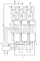
Fig. 1 is the integrally-built figure that the motor drive that first execution mode of the present invention relates to is shown.
Motor drive is connected with motor 5 with DC power supply 1, comprises inverter circuit crowd 2, interrupted ciruit crowd 3, control circuit 4 and position detector 6.
Fig. 2 is the circuit diagram of the details of expression three-phase inverter circuitry 20a.
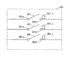
In three-phase inverter circuitry 20a, as shown in Figure 2, switch element Up1 and Ud1 are connected in series, and Vp1 and Vd1 are connected in series, and Wp1 and Wd1 are connected in series.And switch element that these are connected in series and smmothing capacitor C1 are connected in parallel.Smmothing capacitor C1 will remove the noise that is superimposed on this supply voltage from the supply voltage smoothing of DC power supply 1 supply.The tie point WT1 of tie point VT1, Wp1 and the Wd1 of tie point UT1, Vp1 and the Vd1 of Up1 and Ud1 via after the winding 50aU that relates to mutually with U respectively of the switch S U1, SV1, SW1 of the interrupted ciruit 30a that comprises of the interrupted ciruit crowd 3 that states, the winding 50aV that V relates to mutually, the winding 50aW that W relates to mutually be connected.
Three- phase inverter circuitry 20a, 20b, 20c have from DC power supply 1 accept direct-current power supply and supply with the operating condition of three-phase ac power and as short circuit two states of short-circuit condition of state; According to the control that utilizes control circuit 4, switch operating condition and short-circuit condition.At this, so-called short-circuit condition is, two sides of the switch element that as the switch element Up1 of three-phase inverter circuitry 20a and Ud1, is connected in series are set as the state of on-state.In addition; In this execution mode; Switch element Up1, Ud1, Vp1, Vd1, Wp1 and Wd1 become on-state (conducting state) under the situation of the signal input of high level, under the situation of low level signal input, become off-state (dissengaged positions).Three- phase inverter circuitry 20b, 20c have the structure identical with three-phase inverter circuitry 20a.Omission is to the explanation of three- phase inverter circuitry 20b, 20c.
At this, three- phase inverter circuitry 20a, 20b, 20c and DC power supply 1 form series circuit.Specifically, the contact IT1 among the three-phase inverter circuitry 20a is connected with the side of the positive electrode terminal of DC power supply 1, and another contact OT1 is connected with the contact IT1 of three-phase inverter circuitry 20b.And the contact OT1 among the three-phase inverter circuitry 20b is connected with the contact IT1 of three-phase inverter circuitry 20c.In addition, the contact OT1 among the three-phase inverter circuitry 20c is connected with the negative side terminal of DC power supply 1.
Fig. 3 is the circuit diagram that the structure of interrupted ciruit 30a is shown.
At this, about above-mentioned a plurality of systems, below the system corresponding with winding 50a is called a of system, the system corresponding with winding 50b is called the b of system, the system corresponding with winding 50c is called the c of system.For each system, constitute power converter by three-phase inverter and interrupted ciruit.Specifically; The power converter 70a corresponding with a of system is made up of three-phase inverter circuitry 20a and interrupted ciruit 30a; The power converter 70b corresponding with the b of system is made up of three-phase inverter circuitry 20b and interrupted ciruit 30b, and the power converter 70c corresponding with the c of system is made up of three-phase inverter circuitry 20c and interrupted ciruit 30c.
Control circuit 4 is accepted Motor Drive command signal Is and Ns.Is is the signal that the difference of just the changeing/reverse of motor/stop being shown.Ns illustrates the target revolution of motor.Control circuit 4 illustrates at Is under the situation of forward or reverse, carries out drive controlling, makes motor with the direction of rotation shown in the Is, rotate with the revolution shown in the Ns.In addition, illustrate under the situation about stopping, controlling and make the rotation of motor stop at Is.Control circuit 4 switches three- phase inverter circuitry 20a, 20b, the operating condition of 20c, short-circuit condition according to the notice sensing revolution N0 from position detector 6 according to revolution N0, in addition, switches interrupted ciruit 30a, 30b, the conducting state of 30c, dissengaged positions.
In addition, though control circuit 4 is made absolute construction with position detector 6, also can make the structure that control circuit 4 has the function of position detector 6 concurrently.
< action >
Below, the action of the motor drive that this execution mode is related to uses Fig. 4~Fig. 6 and Fig. 8 to describe with the center that is controlled to be that utilizes control circuit 4.
Fig. 4 illustrates the flow chart that circuit connects control.
Fig. 5 is the sequential chart that the control signal under the situation that three-phase inverter circuitry 20a is made as conducting state relates to.
Fig. 6 is the sequential chart that the control signal under the situation that three-phase inverter circuitry 20a is made as short-circuit condition relates to.
Fig. 8 (a) is used for the figure that described by the DC power supply voltage of three dividing potential drops in three-phase inverter circuitry, and Fig. 8 (b) is used for the figure that do not described by the DC power supply voltage under the situation of dividing potential drop in three-phase inverter circuitry.
Up1 among Fig. 5, Fig. 6, Ud1, Vp1, Vd1, Wp1, the Wd1 signal with the switch element Up1 of the three-phase inverter circuitry 20a that is used for control chart 2, Ud1, Vp1, Vd1, Wp1, Wd1 respectively are corresponding.In addition, SU1, SV1, the SW1 among Fig. 5, Fig. 6 and to be used for the signal of switch S U1, SV1, SW1 of the interrupted ciruit 30a of control chart 3 corresponding.H among Fig. 5, Fig. 6, L illustrate high level, the low level of signal, and switch element, switch become connection (conducting) state under the situation of high level, when low level, become disconnection (cut-out) state.In addition, T0~T6 of Fig. 5, Fig. 6 illustrates electrical degree 2 π.Control to the Up1 of Fig. 5, Ud1, Vp1, Vd1, Wp1, Wd1 is the control of in three-phase inverter circuitry, often carrying out usually for DC power supply is transformed to AC power.The state that carries out this control is exactly above-mentioned " operating condition " in the three-phase inverter circuitry.Specifically, Up1, Ud1, Vp1, Vd1, Wp1, Wd1 are switched on during π respectively intermittently.In addition; Up1 and Ud1 are the voltage that is applied in reversed polarity under the situation of high level at Up1; So that Ud1 is a low level; Up1 and Ud1, Vp1 and Vd1 and Wp1 and Wd1 be provided with respectively become simultaneously off-state during so that not short circuit (being commonly referred to as idle time (dead time)).In addition, also apply the voltage of reversed polarity respectively for Vp1 and Vd1, Wp1 and Wd1.In addition, control is connected, broken off to stagger the mutually phase place of 2 π/3 of Up1, Vp1, Wp1.In addition, the SU1 of Fig. 5, SV1, SW1 all are high level, and switch S U1, SV1, SW1 connect (conducting) state.The state that carries out this control is exactly above-mentioned " conducting state " in interrupted ciruit 30a.
In Fig. 6, Up1, Ud1, Vp1, Vd1, Wp1, the whole of Wd1 are high level, and switch element Up1, Ud1, Vp1, Vd1, Wp1, Wd1 all become connection (conducting) state.The state that carries out this control is exactly above-mentioned " short-circuit condition " in three-phase inverter circuitry.In addition, the SU1 of Fig. 6, SV1, SW1 all are low levels, and switch S U1, SV1, SW1 break off (cut-out) state.The state that carries out this control is exactly above-mentioned " dissengaged positions " in interrupted ciruit 30a.
Below, describe based on the flow chart of Fig. 4.
At first, position detector 6 detects the revolution N0 of motor 5, with the revolution N0 notice control circuit 4 (S1) that detects.The detection of this revolution N0 is perhaps every always detection of carrying out at a distance from specific time interval.Control circuit 4 compares (S2) with the revolution N0 of notice with regulation revolution N1.Revolution N0 for the situation below the regulation revolution N1 under (S2: " being "), control circuit 4 is controlled (S3) so that interrupted ciruit 30a, 30b, 30c all become the mode of conducting state.Specifically, separately SU1 of interrupted ciruit 30a, 30b, 30c, SV1, SW1 are according to the sequential chart Be Controlled of Fig. 5.And control circuit 4 is controlled (S4) so that each of three-phase inverter circuitry 20a, 20b, 20c becomes the mode of operating condition.Specifically, three-phase inverter circuitry 20a, 20b, 20c Up1, Ud1, Vp1, Vd1, Wp1, Wd1 separately controlled according to the sequential chart of Fig. 5.According to the control of this S3, S4, the direct voltage of supplying with from DC power supply 1 becomes by the state of three-phase inverter circuitry 20a, 20b and 20c three dividing potential drops.Shown in Fig. 8 (a), three-phase inverter circuitry 20a, 20b, 20c become respectively according to the situation that is generated the three-phase alternating current corrugating by the DC power supply voltage of three dividing potential drops.
In addition; For surpassing regulation revolution N1 (S2: " deny ") and for stipulating under the situation below the revolution N2 (S5: " being "), control circuit 4 is kept the mode of conducting state and is controlled (S6) interrupted ciruit 30a is made as dissengaged positions, interrupted ciruit 30b, 30c at revolution N0.Specifically, carry out control, carry out control based on sequential chart shown in Figure 5 for interrupted ciruit 30b, 30c based on sequential chart shown in Figure 6 for interrupted ciruit 30a.And then control circuit 4 is so that three-phase inverter circuitry 20a becomes the mode of short-circuit condition controls, and the mode of state is controlled (S7) so that three-phase inverter circuitry 20b, 20c keep on the go.Specifically, carry out control, carry out control based on sequential chart shown in Figure 5 for three-phase inverter circuitry 20b, 20c based on sequential chart shown in Figure 6 for three-phase inverter circuitry 20a.According to the control of this S6, S7, the direct voltage of supplying with from DC power supply 1 is applied to three-phase inverter circuitry 20b and 20c via the three-phase inverter circuitry 20a that becomes short-circuit condition.That is the direct voltage of, supplying with from DC power supply 1 is from being become by the state of three-phase inverter circuitry 20b and 20c two dividing potential drops by the state of three-phase inverter circuitry 20a, 20b and 20c three dividing potential drops.Three-phase inverter circuitry 20b, 20c become respectively according to the situation that is generated the three-phase alternating current corrugating by the DC power supply voltage after two dividing potential drops.Thereby, and being applied in DC power supply by the compared of three voltage after partial, rotary driving motor 5 more at high speed.
In addition, surpass at revolution N0 under the situation of regulation revolution N2 (S5: " denying "), control circuit 4 is kept the mode of conducting state and is controlled (S8) interrupted ciruit 30a, 30b are made as dissengaged positions, interrupted ciruit 30c.Specifically, carry out control, carry out control based on sequential chart shown in Figure 5 for interrupted ciruit 30c based on sequential chart shown in Figure 6 for interrupted ciruit 30a, 30b.And then control circuit 4 is so that three-phase inverter circuitry 20a, 20b become the mode of short-circuit condition controls, and the mode of state is controlled (S9) so that three-phase inverter circuitry 20c keeps on the go.Specifically, carry out control, carry out control based on sequential chart shown in Figure 5 for three-phase inverter circuitry 20c based on sequential chart shown in Figure 6 for three-phase inverter circuitry 20a, 20b.According to the control of this S8, S9, shown in Fig. 8 (b), the direct voltage of supplying with from DC power supply 1 is applied to three-phase inverter circuitry 20c via the three-phase inverter circuitry 20a that becomes short-circuit condition, 20b.That is the direct voltage of, supplying with from DC power supply 1 is from being become not by the state of dividing potential drop by the state of three-phase inverter circuitry 20b and 20c two dividing potential drops.Three-phase inverter circuitry 20c becomes according to the situation that is not generated the three-phase alternating current corrugating by the DC power supply voltage of dividing potential drop.Thereby, and be applied in DC power supply by the compared of two voltage after partial, can be further rotary driving motor 5 more at high speed.
Through implementing above-mentioned control, thereby can the sufficient direct voltage of necessity be applied to a plurality of three-phase inverter circuitry according to the revolution of motor 5.Thereby, can significantly reduce size that depends on direct voltage and the switching loss that when switch motion, produces.In addition; Because can in motor drive,, the voltage that is applied to the switch element that constitutes three-phase inverter circuitry be reduced in the less zone of the high ratio of revolutions of usage frequency; So can seek the high lifeization of switch element, and then can seek the reliability lifting of motor drive.In addition; Because three- phase inverter circuitry 20a, 20b, 20c make the structure that is connected with winding 50a, 50b, 50c via a plurality of interrupted ciruit 30a, 30b, 30c respectively; So can break off the path (three-phase inverter circuitry and winding) that becomes abnormality by interrupted ciruit in that any of three- phase inverter circuitry 20a, 20b, 20c or winding 50a, 50b, 50c detected under the unusual situation.Thereby, even in the Motor Drive state, produce the abnormality that causes by defective insulation etc., also can continue the Motor Drive state, can avoid the state of affairs that is difficult to expect.
In addition, revolution N1 is the slightly little revolution of specific revolution N1 '.N1 ' is; Revolution at motor 5 surpasses under the situation of N1 '; Because the influence of the inverse electromotive force that in motor 5, produces becomes with the revolution that can not make motor 5 rotations according to the AC supply voltage that in three- phase inverter circuitry 20a, 20b, 20c, is generated by the DC power supply voltage after three dividing potential drops.In addition, revolution N2 is the slightly little revolution of specific revolution N2 '.N2 ' is; Revolution at motor 5 surpasses under the situation of N2 '; Because the influence of the inverse electromotive force that in motor 5, produces becomes with the revolution that can not make motor 5 rotations according to the AC supply voltage that in three- phase inverter circuitry 20b, 20c, is generated by the DC power supply voltage after two dividing potential drops.The concrete numerical value of N1, N1 ', N2, N2 ' is according to the specification of motor etc. and different.
2. second execution mode
In this execution mode, detect the temperature of power converter, avoid the too high abnormal operation that causes, fault because the temperature of power converter becomes, seek the lifting of high lifeization He the motor drive whole reliability of power converter.
Figure 10 is the integrally-built figure that the motor drive that second execution mode of the present invention relates to is shown.
Motor drive shown in Figure 10 is the structure that the inverter circuit crowd 2 of motor drive shown in Figure 1, power converter 70a~70c and control circuit 4 is replaced into inverter circuit crowd 200, power converter 71a~71c and control circuit 400 respectively.
Figure 11 is the figure that the circuit structure of three-phase inverter circuitry 21a is shown.
Three-phase inverter circuitry 21a is the structure that three-phase inverter circuitry 20a has been increased Temperature Detector Up1-_t, Ud1-_t, Vp1-_t, Vd1-_t, Wp1-_t, Wd1-_t.Because three- phase inverter circuitry 21b, 21c have the structure identical with three-phase inverter circuitry 21a, so, below be that the center describes with three-phase inverter circuitry 21a and power converter 71a.
Below action is described.
Figure 12 is the figure that short circuit inverter circuit change control is shown.
At first, detect the temperature of power converter 71a, 71b, 71c.More particularly; Temperature Detector Up1-_t, Ud1-_t, Vp1-_t, Vd1-_t, Wp1-_t, Wd1-_t sense switch element Up1-, Ud1, Vp1-, Vd1, Wp1, Wd1 temperature separately are to control circuit 400 feedback switch component temperature information (S21).Control circuit 400 becomes under the situation of short-circuit condition at least one power converter; More particularly the three-phase inverter circuitry at least one power converter becomes under the situation of short-circuit condition; (S22: " being ") changes to operating condition (S23) with the three-phase inverter circuitry in the power converter that becomes short-circuit condition up to now under the situation that has switch element temperature big switch element than set point of temperature T1.And the interrupted ciruit that will be connected with the three-phase inverter circuitry in the power converter that changes to operating condition is made as connection status (S24).And the interrupted ciruit that will be connected with the three-phase inverter circuitry in the power converter that comprises the switch element bigger than set point of temperature T1 is made as dissengaged positions (S25).And, will comprise that the three-phase inverter circuitry in the power converter of the switch element bigger than set point of temperature T1 changes to short-circuit condition (S26).
According to above control, can avoid power converter more specifically to say so the state of affairs that the temperature of switch element becomes too high can be sought the lifting of reliability of high lifeization and the motor drive of power converter, switch element.
In addition; Preferably in power converter; Carrying out three-phase inverter circuitry being made as the processing of short-circuit condition and interrupted ciruit is being made as under the situation of two processing of processing of dissengaged positions; At first carry out interrupted ciruit is made as the processing of dissengaged positions, then, carry out three-phase inverter circuitry is made as the processing of short-circuit condition.
3. the 3rd execution mode
Though the temperature of sense switch element is as the temperature of power converter in second execution mode, this execution mode detects the temperature of the temperature of smmothing capacitor as power converter.
Figure 13 is the integrally-built figure that the motor drive that the 3rd execution mode of the present invention relates to is shown.
Motor drive shown in Figure 13 is the structure that the inverter circuit crowd 2 of motor drive shown in Figure 1, power converter 70a~70c and control circuit 4 is replaced into inverter circuit crowd 201, power converter 72a~72c and control circuit 401 respectively.
Because the structure of three- phase inverter circuitry 22b, 22c is identical with the structure of three-phase inverter circuitry 21a, so, below only three-phase inverter circuitry 22a and power converter 72a are described.
Figure 14 is the figure that the circuit structure of three-phase inverter circuitry 22a is shown.
The point that three-phase inverter circuitry 22a is different with three-phase inverter circuitry 20a is to have Temperature Detector C1_t at smmothing capacitor C1.Temperature Detector C1_t detects the temperature of smmothing capacitor, to control circuit 401 feedback smmothing capacitor temperature informations.Control circuit 401 is under the smoothing capacity actuator temperature situation bigger than set point of temperature T2, and the mode that switches to the three-phase inverter circuitry of other power converter with the three-phase inverter circuitry of the power converter that will become short-circuit condition is controlled.This control is the temperature controlling that the temperature controlling of measuring switch element in S23~S26 shown in Figure 12 is become the measurement smmothing capacitor, does not have the place different with the control of Figure 12 in others.
In general, compare with the situation that in three-phase inverter circuitry, becomes short-circuit condition, smmothing capacitor becomes high temperature more easily under the situation of implementing PWM control.Thereby according to this structure, can avoid power converter more specifically to say so the state of affairs that the temperature of smmothing capacitor becomes too high can be sought the high lifeization of power converter, smmothing capacitor and the reliability of motor drive and promoted.
4. the 4th execution mode
Though the temperature of sense switch element is as the temperature of power converter in second execution mode; In the 3rd execution mode, detect the temperature of the temperature of smmothing capacitor, but this execution mode detects the temperature of the temperature of interrupted ciruit as power converter as power converter.
Figure 15 is the integrally-built figure that the motor drive that the 4th execution mode of the present invention relates to is shown.
Motor drive shown in Figure 15 is the structure that the interrupted ciruit crowd 3 of motor drive shown in Figure 1, power converter 70a~70c and control circuit 4 is replaced into interrupted ciruit crowd 300, power converter 73a~73c and control circuit 402 respectively.
Figure 16 is the figure that the circuit structure of interrupted ciruit 31a is shown.
The point that interrupted ciruit 31a is different with interrupted ciruit 30a is to have Temperature Detector SU1_t, SV1_t, SW1_t.Temperature Detector SU1_t, SV1_t, SW1_t be sense switch SU1, SV1, SW1 temperature separately respectively, feeds back to control circuit 402 as switch temperature information.Control circuit 402 is controlled with the mode of the three-phase inverter circuitry that is switching to short-circuit condition under the situation bigger than set point of temperature T3 of the temperature shown in the switch temperature information.
Figure 17 is the flow chart that the processing of controlling based on the short circuit inverter circuit change of switch temperature information is shown.
At first, by with running in power converter in the temperature (S41) of each switch of Temperature Detector detection of possessing of the interrupted ciruit that is connected of three-phase inverter circuitry.In addition, Temperature Detector be not limited to turn round in power converter in the Temperature Detector that possesses of the interrupted ciruit that is connected of three-phase inverter circuitry, the Temperature Detector that also can be possessed by all interrupted ciruits is measured the temperature of each switch.
And the interrupted ciruit that will be connected with the three-phase inverter circuitry in the power converter that comprises the switch that surpasses set point of temperature T3 is made as dissengaged positions (S45).And, will comprise that the three-phase inverter circuitry in the power converter of the switch that surpasses set point of temperature T3 changes to short-circuit condition (S46).
According to this control, can avoid power converter more specifically to say so the state of affairs that the temperature of switch becomes too high can be sought the high lifeization of power converter, switch and the reliability lifting of motor drive.
5. the 5th execution mode
Figure 18 is the integrally-built figure that the motor drive that the 5th execution mode of the present invention relates to is shown.
Motor drive shown in Figure 180 is the structure that the inverter circuit crowd 2 of motor drive shown in Figure 1, interrupted ciruit crowd 3, power converter 70a~70c and control circuit 4 is replaced into inverter circuit crowd 202, interrupted ciruit crowd 301, power converter 74a~74c and control circuit 403 respectively.
According to this structure; Because be always common operating condition with formation, can be supplied to and do not compared by the switch element of the three-phase inverter circuitry 23c of the supply voltage of dividing potential drop; The switch element that constitutes three- phase inverter circuitry 23a and 23b can be made up of relatively lower withstand voltage switch element, thus with situation about all constituting by the withstand voltage switch element of high specific energy reduction inverter losses mutually.
In addition, through three-phase inverter circuitry 23c being connected interrupted ciruit, thereby can cut down the conduction loss of interrupted ciruit.So, can seek the high efficiency and the cost degradation of motor drive.
In addition; In Figure 18; As long as will constitute the current capacity of the switch element of three-phase inverter circuitry 23c makes bigger than the current capacity of the switch element that constitutes three- phase inverter circuitry 23a and 23b; Even then become under the situation of high rotation, also can realize suppressing the stable driving of the heating of switching loss at motor.Thereby, can seek the high efficiency of motor drive and the lifting of reliability.
6. the 6th execution mode
Figure 19 is the integrally-built figure that the motor drive that the 6th execution mode of the present invention relates to is shown.
Motor drive shown in Figure 19 is the structure that the interrupted ciruit crowd 3 of motor drive shown in Figure 1, power converter 70a~70c and control circuit 4 is replaced into interrupted ciruit crowd 302, power converter 75a~75c and control circuit 404 respectively.
Figure 20 is the figure that the circuit structure of interrupted ciruit 32a is shown.
The point that interrupted ciruit 32a is different with interrupted ciruit 30a is to have voltage detector SU1_v, SV1_v, SW1_v.Voltage detector SU1_v, SV1_v, SW1_v sense switch SU1, SV1, SW1 voltage between terminals value separately are to control circuit 404 feedbacks.
According to this structure, can under the situation of the current sensor that does not use high price and high temperature dyskinesia, obtain current value.Thereby cost degradation and the reliability that can seek motor drive promote.
7. the 7th execution mode
Figure 21 is the integrally-built figure that the motor drive that the 7th execution mode of the present invention relates to is shown.
Motor drive shown in Figure 21 has the structure that the inverter circuit crowd 2 of motor drive shown in Figure 1, power converter 70a~70c and control circuit 4 is replaced into inverter circuit crowd 203, power converter 76a~76c and control circuit 405 respectively.
Figure 22 is the figure that the circuit structure of three-phase inverter circuitry 24a is shown.
The point that three-phase inverter circuitry 24a is different with three-phase inverter circuitry 20a is to have discharge resistance R1 and uses switch element D1 with discharge.
Figure 23 is the sequential chart under the situation of the short circuit action of implementing three-phase inverter circuitry.
Whether control circuit 405 is judged bigger than the regulation revolution by the revolution of position detector 6 detection motor 5.Under the big situation of the ratio of revolutions regulation revolution of motor, the output short-circuit command signal (signal that control circuit is inner.Not shown.), make at least one three-phase inverter circuitry carry out the short circuit action.According to this short circuit command signal, control circuit 405 is to three-phase inverter circuitry 24a output discharge signal (DS1) shown in Figure 23.Discharge is accepted discharge signal (DS1) with switch element D1, becomes on-state at the appointed time.Become on-state through discharge with switch element, thereby the electric charge of smmothing capacitor is discharged.At this, the value of discharge resistance R1 is so that flow through discharge and become discharge with the current value of switch element and set with the following mode of the maximum current capacity of switch element.Control circuit 405 is after the electric charge of smmothing capacitor is fully discharged, and will discharge is made as off-state with switch element, almost simultaneously switch element Up1 and Ud1 is made as on-state.
Through such control, thereby can make three-phase inverter circuitry carry out suppressing to flow through the situation of excessive electric current under the situation of short circuit action from smmothing capacitor.Thereby the reliability that can seek motor drive promotes.
8. other variation
In addition, though describe the present invention based on above-mentioned execution mode, the present invention is not limited to above-mentioned execution mode, sure various changes in addition in the scope that does not break away from main idea of the present invention.
(1) though in the first embodiment, be illustrated with the example that under the situation that three-phase inverter circuitry is made as short-circuit condition, three-phase all is made as short-circuit condition,, also can only be made as short-circuit condition mutually with one.Fig. 7 (a) only shows the U among the three-phase inverter circuitry 20a is made as short-circuit condition mutually, accompanies therewith, and the switch S U1 that only U is related to mutually is made as the sequential chart under the situation of dissengaged positions.But, three- phase inverter circuitry 20a, 20b, 20c are being made as under the situation of short-circuit condition, preferably be made as short-circuit condition more than mutually with two, most preferably three-phase all is made as short-circuit condition.This is because can reduce the connection resistance value of conducting through short-circuit condition, can seek loss and reduce.
(2) though in above-mentioned variation (1), show under the situation that three-phase inverter circuitry 20a is made as short-circuit condition, be not limited thereto, also can whenever switch the phase that is made as short-circuit condition at a distance from the stipulated time with the example of U phase short circuit.Fig. 7 (b) is illustrated in every separated stipulated time according to the sequential chart under the situation of the phase of the order switching short circuit of U phase, V phase, W phase.Because through being set as like this, thereby can do one's utmost to reduce the time that switch element becomes short-circuit condition, so the reliability that can seek the high lifeization of switch element and then can seek motor drive promotes.
In addition; If as second execution mode in three-phase inverter circuitry to U phase, V phase, W mutually among the structure of the two electric circuit inspection temperature that relate to more than mutually; So also can three-phase inverter circuitry 20a be made as under the situation of short-circuit condition; The circuit that will not surpass set point of temperature to the temperature of each electric circuit inspection that relates to mutually is made as short-circuit condition, and the more than one circuit that relates to mutually below the set point of temperature is made as short-circuit condition.Thus, can avoid the short circuit that causes by the path that is considered to abnormality, can be by the path short circuit reliably of normal condition.
In addition, can be under the situation of short-circuit condition also at least one of three-phase inverter circuitry, every through the stipulated time, replace the inverter circuit of short-circuit condition and will not be that other inverter circuit of short-circuit condition is made as short-circuit condition.Through being set as like this, thus the high lifeization that can seek switch element, and then the reliability that can seek motor drive promotes.
(3) in the switch element that constitutes three- phase inverter circuitry 20a, 20b, 20c, also can the different switch element of operating characteristic.For example, the order that preferably is set as according to three- phase inverter circuitry 20a, 20b, 20c makes the connection resistance.Through being set as like this, thereby carry out to reduce the conduction loss of the switch element of the three-phase inverter circuitry that becomes short-circuit condition under the situation of high speed rotating action, high efficiency motor drive can be provided at motor 5.
(4) also can use following interrupted ciruit for interrupted ciruit 30a, 30b, 30c.
Fig. 9 (a), Fig. 9 (b) are the figure that the circuit structure of the interrupted ciruit that this variation relates to is shown respectively.
Interrupted ciruit shown in Fig. 9 (a) has break-and-make switch element SU1a, SV1a, SW1a.Interrupted ciruit has break-and-make switch element SU1b, SV1b, SW1b shown in Fig. 9 (b).
Break-and-make switch element SU1a, SV1a, SW1a, SU1b, SV1b, SW1b all are made up of semiconductor switch.In addition, break-and-make switch element SU1a, SV1a, SW1a reverse parallel connection connect.Break-and-make switch element SU1b, SV1b, SW1b conducting direction are opposite and be connected in series.Through being set as like this, thereby compare, can seek low cost and miniaturization with the situation that constitutes the break-and-make switch element by relay etc.And then, can seek high-speed responseization because compare, so can implement the change action of motor drive glibly with relay etc.In addition, because can fast shut-off three-phase inverter circuitry and winding when motor drive unusual, so also can seek the high reliabilityization of motor drive.In addition, the semiconductor switch that constitutes break-and-make switch can be any of bipolar transistors (bipolar transistor) such as unipolar transistors such as MOSFET (unipolar transistor) or IGBT etc.
(5) in above-mentioned execution mode, make the number that is made as the three-phase inverter circuitry of short-circuit condition according to the revolution change of motor.But, be not limited to the revolution of motor, also can make the number that is made as the three-phase inverter circuitry of short-circuit condition according to other operate condition change of motor.
A. for example, can make the number that torque (motor current) change according to motor is made as the three-phase inverter circuitry of short-circuit condition.
Under the big situation of required torque (motor current), can become big from the DC electric current of battery.Consequently, battery can generate heat.For fear of this situation, under the big situation of required torque, three three-phase inverter circuitry are made as operating condition, the mode of supply voltage three dividing potential drops is switched.Because three three-phase inverters become be connected in series, thus with compare with the situation of a three-phase inverter drive motor, can obtain big torque with low current.
B. for example, can switch the number of the three-phase inverter circuitry that is made as operating condition according to the current phase of motor.
For example, in the structure of utilizing the reluctance torque of motor (reluctance torque), the situation of the current phase of control motor is arranged.Specifically make current phase carry out the phase angle in advance, carry out the phase angle in advance through making it, thereby become the situation that applies the opposing magnetic field to the permanent magnet that is disposed at the rotor that constitutes motor.When such control is excessive, the danger of demagnetization is arranged.This moment is through applying the opposing magnetic field to permanent magnet, thereby can be suppressed at the reverse voltage (reverse voltage ∝ flux change) that produces between the terminal of motor.
Specifically, when under slow speed, utilizing reluctance torque to carry out Motor Drive, (mainly consider the high temperature demagnetization in the demagnetization danger that permanent magnet occurs.) situation under, the phase angle that stops current phase is in advance.The reverse voltage that can suppress before in advance at the phase angle that stops current phase at this moment, becomes and can not suppress.
Thereby; Because supply voltage is increased more than the big amount of reverse voltage change, so, for example control as follows: two three-phase inverter circuitry are made as short-circuit condition; Generate three-phase alternating voltage with a three-phase inverter circuitry according to the voltage that does not have dividing potential drop, supply with to motor.
(6) though respectively in second execution mode, the 3rd execution mode and the 4th execution mode; The temperature of sense switch element, smmothing capacitor and the interrupted ciruit situation as the detection of the temperature of power converter is illustrated; But be not limited thereto, also can make the temperature of other inscape that detects power converter.For example, can measure the temperature of the wiring in the power converter.
(7) though respectively in second execution mode, the 3rd execution mode and the 4th execution mode; The structure that the object (switch element, smmothing capacitor or interrupted ciruit) of a detected temperatures is possessed a Temperature Detector is illustrated; But be not limited thereto, as long as constitute with the mode of the temperature that can seek power converter.For example, can possess a Temperature Detector to a plurality of temperature detection objects.As an example, if switch element and smmothing capacitor near the such situation of configuration, just need only Temperature Detector of position configuration therebetween, the temperature that detects this position gets final product.In addition, also can between power converter and other power converter, dispose Temperature Detector, measure the temperature of the position that disposes Temperature Detector.That is, configuration several temperature detector, this can wait according to quantity, the configuration of temperature detection object and change.
(8) also can make up above-mentioned execution mode and above-mentioned variation respectively.
Utilizability on the industry
Because motor drive of the present invention can be sought high efficiency, Towards Higher Voltage with easy structure, also has electricity generation system of wind generator system etc. etc. so be fit to comprise all motor drives of hybrid power formula (hybrid) electric automobile and electric automobile, the motor compressor of strong request miniaturization, electric-powered steering wheel, elevator.
Description of reference numerals
1: DC power supply, 2: inverter circuit crowd, 3: interrupted ciruit crowd, 4: control circuit; 5: motor, 6: position detector, 20a, 20b, 20c: three-phase inverter circuitry, 30a, 30b, 30c: interrupted ciruit; 32a, 32b, 32c: interrupted ciruit, 50a, 50b, 50c: winding, Up1, Ud1: switch element, Vp1, Vd1: switch element; Wp1, Wd1: switch element, C1: smmothing capacitor, SU1, SV1, SW1: switch.
Claims (10)
1. motor drive accepts from DC power supply that electric power is supplied with and the motor of the excitation winding of a plurality of systems drives to possessing independently, wherein,
Said motor drive comprises control circuit and a plurality of power converters corresponding respectively with said a plurality of systems,
Said each power converter comprises inverter circuit, interrupted ciruit and Temperature Detector, and wherein, said interrupted ciruit is inserted between the excitation winding and said inverter circuit of said correspondence,
Said a plurality of inverter circuit and said DC power supply are connected in series, and each inverter circuit carries out electric power to the excitation winding of the system of correspondence and supplies with under the situation that is not short-circuit condition,
The operate condition of the said motor of said control circuit sensing; The inverter circuit that will relate to according to the power converter of the definite number of the operate condition of said motor is made as short-circuit condition; And interrupted ciruit is made as dissengaged positions; Thus, make the service voltage of said DC power supply supply to the inverter circuit that is not short-circuit condition, exist under the situation of detected temperatures that detects by said Temperature Detector above the power converter of set point of temperature; The inverter circuit of this power converter is made as short-circuit condition; And cut off the interrupted ciruit of this power converter, and the inverter circuit that will be surpassed other power converter of set point of temperature by the detected temperatures that said Temperature Detector detects is made as operating condition, and interrupted ciruit is made as connection status.
2. motor drive according to claim 1, wherein,
Said a plurality of inverter circuit is formed by a plurality of switch element bridge joints respectively,
Said Temperature Detector is measured the temperature of each switch element.
3. motor drive according to claim 1, wherein,
Said a plurality of inverter circuit possesses smmothing capacitor respectively,
Said Temperature Detector is measured the temperature of said smmothing capacitor.
4. motor drive according to claim 1, wherein,
Said interrupted ciruit possesses a plurality of switch elements,
Said Temperature Detector is measured the temperature of each said switch element.
5. motor drive according to claim 1, wherein,
Said a plurality of inverter circuit is respectively a three-phase inverter circuitry,
Said excitation winding is formed by the winding star-star connection of the amount of three-phase,
Said Temperature Detector detects the temperature of each each circuit that relates to mutually,
Said control circuit is made as under the situation of short-circuit condition at the inverter circuit that any power converter is related to, and makes the detected temperatures that is detected by Temperature Detector not surpass at least one short circuit that relates to mutually of set point of temperature.
6. motor drive according to claim 1, wherein,
Said a plurality of inverter circuit is respectively a three-phase inverter circuitry, forms by a plurality of switch element bridge joints respectively,
Said excitation winding is formed by the winding star-star connection of the amount of three-phase,
Said control circuit is being made as three-phase inverter circuitry under the situation of short-circuit condition, and at least one switch element that is connected in series that relates to mutually among the three-phase is made as conducting state respectively.
7. motor drive according to claim 1, wherein,
Said control circuit is not made as short-circuit condition with the specific inverter circuit among said a plurality of inverter circuits,
Formation can be made as the switch element of the inverter circuit of short-circuit condition and compare withstand voltage low with the switch element that constitutes said specific inverter circuit.
8. motor drive according to claim 1, wherein,
Said control circuit is not made as short-circuit condition with the specific inverter circuit among said a plurality of inverter circuits,
It is little that switch element and the switch element that constitutes said specific inverter circuit that formation can be made as the inverter circuit of short-circuit condition compared the maximum current capacity.
9. motor drive according to claim 1, wherein,
Said interrupted ciruit is made up of switch element, possesses the voltage detector of the connection voltage of measuring said switch element,
Said control circuit uses the connection voltage detecting of said switch element to flow through the magnitude of current of said switch element.
10. motor drive according to claim 1, wherein,
Said a plurality of inverter circuit is respectively a three-phase inverter circuitry; Being connected in parallel by bridge circuit, smmothing capacitor and discharge circuit respectively forms, and wherein, said bridge circuit is formed by a plurality of switch element bridge joints; Said discharge circuit is connected in series with switch element with discharge by discharge resistance and forms
Said control circuit is before being made as short-circuit condition for each inverter circuit is made as short-circuit condition with said bridge circuit; Through said discharge is made as on-state at the appointed time with switch element, thereby discharge to putting aside in the electric charge of said smmothing capacitor.
Applications Claiming Priority (3)
| Application Number | Priority Date | Filing Date | Title |
|---|---|---|---|
| JP2011021929 | 2011-02-03 | ||
| JP2011-021929 | 2011-02-03 | ||
| PCT/JP2012/000711 WO2012105266A1 (en) | 2011-02-03 | 2012-02-02 | Motor drive device |
Publications (2)
| Publication Number | Publication Date |
|---|---|
| CN102812631A true CN102812631A (en) | 2012-12-05 |
| CN102812631B CN102812631B (en) | 2013-12-18 |
Family
ID=46602488
Family Applications (1)
| Application Number | Title | Priority Date | Filing Date |
|---|---|---|---|
| CN2012800010322A Active CN102812631B (en) | 2011-02-03 | 2012-02-02 | Motor drive device |
Country Status (4)
| Country | Link |
|---|---|
| US (1) | US8508180B2 (en) |
| JP (1) | JP5095042B1 (en) |
| CN (1) | CN102812631B (en) |
| WO (1) | WO2012105266A1 (en) |
Cited By (4)
| Publication number | Priority date | Publication date | Assignee | Title |
|---|---|---|---|---|
| CN104943110A (en) * | 2014-03-31 | 2015-09-30 | 住友重机械工业株式会社 | Injection molding machine |
| CN105048888A (en) * | 2015-08-18 | 2015-11-11 | 重庆大学 | Switching device of permanent magnet synchronous motor windings |
| CN105245154A (en) * | 2015-10-26 | 2016-01-13 | 大工科技(上海)有限公司 | Driving system and method |
| CN110661431A (en) * | 2018-06-29 | 2020-01-07 | 北京天诚同创电气有限公司 | Wind power converter and control method and control device thereof |
Families Citing this family (17)
| Publication number | Priority date | Publication date | Assignee | Title |
|---|---|---|---|---|
| FR2987705B1 (en) * | 2012-03-02 | 2016-11-25 | Alstom Transport Sa | SYNCHRONOUS ELECTRIC MACHINE SUPPLY CHAIN, ELECTRICAL TRACTION SYSTEM COMPRISING SUCH A CHAIN, AND METHOD FOR CONTROLLING SUCH A CHAIN |
| JP5803951B2 (en) * | 2013-02-08 | 2015-11-04 | 株式会社デンソー | Rotating electric machine drive system |
| WO2014196065A1 (en) * | 2013-06-06 | 2014-12-11 | 株式会社安川電機 | Overvoltage protection apparatus and overvoltage protection system |
| CN104584423B (en) * | 2013-08-12 | 2017-06-13 | 日本精工株式会社 | Controller for motor, electric power-assisted steering apparatus and vehicle using the controller for motor |
| DE102013218799A1 (en) * | 2013-09-19 | 2015-03-19 | Siemens Aktiengesellschaft | Modular power converter |
| US20150249419A1 (en) * | 2014-02-28 | 2015-09-03 | Kia Motors Corporation | System and method for controlling inverter |
| JP6402567B2 (en) | 2014-10-03 | 2018-10-10 | セイコーエプソン株式会社 | Circuit device and electronic device |
| JP6217667B2 (en) * | 2015-02-19 | 2017-10-25 | 株式会社豊田自動織機 | Electric compressor |
| EP3131198B1 (en) * | 2015-08-10 | 2022-06-08 | Goodrich Actuation Systems Limited | Control strategy of a dual lane fault tolerant permanent magnet motor to reduce drag torque under fault condition |
| DE102015216007A1 (en) | 2015-08-21 | 2017-02-23 | Lenze Drives Gmbh | drive system |
| JP6560185B2 (en) * | 2016-12-06 | 2019-08-14 | ミネベアミツミ株式会社 | Motor drive control device and control method of motor drive control device |
| CN110521093B (en) * | 2017-03-31 | 2021-08-31 | 日本电产株式会社 | Motor and electric power steering device |
| WO2019036506A1 (en) * | 2017-08-15 | 2019-02-21 | Quanten Technologies, Inc. | Motor system with distributed winding structures |
| CN111095778B (en) * | 2017-09-28 | 2023-12-08 | 株式会社爱信 | Inverter control device |
| DE102018219293A1 (en) * | 2018-11-12 | 2020-05-14 | Kaco New Energy Gmbh | Inverter |
| US11063535B2 (en) * | 2019-09-13 | 2021-07-13 | Ford Global Technologies, Llc | Steering motor brake |
| JP7468377B2 (en) * | 2021-01-22 | 2024-04-16 | 株式会社デンソー | Rotating electric machine control device |
Citations (6)
| Publication number | Priority date | Publication date | Assignee | Title |
|---|---|---|---|---|
| JPS4817557U (en) * | 1971-07-12 | 1973-02-27 | ||
| JPH10225181A (en) * | 1997-02-07 | 1998-08-21 | Mitsubishi Electric Corp | Ac power supplier and ac motor |
| JP2000116149A (en) * | 1998-10-06 | 2000-04-21 | Meidensha Corp | High-frequency power supply |
| JP2003333862A (en) * | 2002-05-15 | 2003-11-21 | Toshiba Corp | Power-converting device |
| CN101040432A (en) * | 2005-01-25 | 2007-09-19 | 三菱电机株式会社 | Electric car controller |
| JP2009278827A (en) * | 2008-05-16 | 2009-11-26 | Ihi Corp | Drive assembly |
Family Cites Families (12)
| Publication number | Priority date | Publication date | Assignee | Title |
|---|---|---|---|---|
| JPS4817557Y1 (en) * | 1968-05-04 | 1973-05-19 | ||
| JPS56139084A (en) * | 1980-03-31 | 1981-10-30 | Toshiba Corp | Control system of ac/dc converter |
| JPH0568301A (en) * | 1991-09-10 | 1993-03-19 | Toshiba Toransupooto Eng Kk | Auxiliary power supply for vehicle |
| JP3296588B2 (en) | 1992-05-11 | 2002-07-02 | 株式会社日立製作所 | Inverter device |
| JP2000004504A (en) | 1998-06-15 | 2000-01-07 | Hitachi Ltd | Control method of electric torque converter |
| JP2000245005A (en) * | 1999-02-18 | 2000-09-08 | Toshiba Corp | Drive controller for rolling stock |
| JP4559665B2 (en) | 2001-06-29 | 2010-10-13 | 株式会社東芝 | Electric motor drive control device |
| JP4397244B2 (en) | 2004-02-10 | 2010-01-13 | トヨタ自動車株式会社 | Inverter device |
| JP2006129668A (en) | 2004-11-01 | 2006-05-18 | Honda Motor Co Ltd | Motor controller |
| JP2009050042A (en) | 2007-08-13 | 2009-03-05 | Yokohama National Univ | Switch inverter, and control method of a plurality of three phase loads |
| JP4969547B2 (en) * | 2008-10-14 | 2012-07-04 | トヨタ自動車株式会社 | Control device and charge control method |
| JP2010124570A (en) * | 2008-11-18 | 2010-06-03 | Toshiba Carrier Corp | Power conversion device |
-
2012
- 2012-02-02 JP JP2012530798A patent/JP5095042B1/en active Active
- 2012-02-02 CN CN2012800010322A patent/CN102812631B/en active Active
- 2012-02-02 US US13/637,136 patent/US8508180B2/en active Active
- 2012-02-02 WO PCT/JP2012/000711 patent/WO2012105266A1/en active Application Filing
Patent Citations (6)
| Publication number | Priority date | Publication date | Assignee | Title |
|---|---|---|---|---|
| JPS4817557U (en) * | 1971-07-12 | 1973-02-27 | ||
| JPH10225181A (en) * | 1997-02-07 | 1998-08-21 | Mitsubishi Electric Corp | Ac power supplier and ac motor |
| JP2000116149A (en) * | 1998-10-06 | 2000-04-21 | Meidensha Corp | High-frequency power supply |
| JP2003333862A (en) * | 2002-05-15 | 2003-11-21 | Toshiba Corp | Power-converting device |
| CN101040432A (en) * | 2005-01-25 | 2007-09-19 | 三菱电机株式会社 | Electric car controller |
| JP2009278827A (en) * | 2008-05-16 | 2009-11-26 | Ihi Corp | Drive assembly |
Cited By (6)
| Publication number | Priority date | Publication date | Assignee | Title |
|---|---|---|---|---|
| CN104943110A (en) * | 2014-03-31 | 2015-09-30 | 住友重机械工业株式会社 | Injection molding machine |
| CN104943110B (en) * | 2014-03-31 | 2018-09-11 | 住友重机械工业株式会社 | Injection (mo(u)lding) machine |
| CN105048888A (en) * | 2015-08-18 | 2015-11-11 | 重庆大学 | Switching device of permanent magnet synchronous motor windings |
| CN105245154A (en) * | 2015-10-26 | 2016-01-13 | 大工科技(上海)有限公司 | Driving system and method |
| CN110661431A (en) * | 2018-06-29 | 2020-01-07 | 北京天诚同创电气有限公司 | Wind power converter and control method and control device thereof |
| CN110661431B (en) * | 2018-06-29 | 2020-12-29 | 北京天诚同创电气有限公司 | Wind power converter and control method and control device thereof |
Also Published As
| Publication number | Publication date |
|---|---|
| JP5095042B1 (en) | 2012-12-12 |
| CN102812631B (en) | 2013-12-18 |
| US8508180B2 (en) | 2013-08-13 |
| US20130026968A1 (en) | 2013-01-31 |
| JPWO2012105266A1 (en) | 2014-07-03 |
| WO2012105266A1 (en) | 2012-08-09 |
Similar Documents
| Publication | Publication Date | Title |
|---|---|---|
| CN102812631B (en) | Motor drive device | |
| JP4968698B2 (en) | Electric motor control device | |
| TWI383575B (en) | Winding switch of AC motor and its winding switching system | |
| JP6169203B1 (en) | Electric motor control apparatus and electric motor control method | |
| CN110383677B (en) | Motor drive device and refrigeration cycle applicable equipment | |
| JP4752772B2 (en) | AC motor winding switching device and winding switching system thereof | |
| JP4709580B2 (en) | Railway vehicle drive control device | |
| JP2009303298A (en) | Ac motor device | |
| JP5441481B2 (en) | Inverter device failure diagnosis method | |
| JP2014192950A (en) | Power converter | |
| CN102570936A (en) | Rotator control device, rotator system, vehicle, electric car and electric generation system | |
| JP5606506B2 (en) | Drive control device and drive control method | |
| JP4772104B2 (en) | Power converter | |
| JP6426465B2 (en) | Power converter | |
| JP2008011670A (en) | Inverter system | |
| CN110663170B (en) | Driving device for multi-group multiphase rotary motor | |
| CN108336942A (en) | Three phase electric machine driving circuit | |
| Rana et al. | A fault-tolerant power converter with multi-switch fault diagnosis and repair capability for 4-phase 8/6 SRM drives | |
| JP2013511247A (en) | Inverter | |
| JP2018098826A (en) | Power supply device for vehicle and control method of the same | |
| JP2014165956A (en) | Rotary electric machine drive device | |
| JP6250090B2 (en) | AC rotating machine control device and control method | |
| JP5673114B2 (en) | Inverter device and electric motor drive system | |
| JP6305495B1 (en) | Inverter control device and inverter control method | |
| JP2009219225A (en) | Vehicle driving system |
Legal Events
| Date | Code | Title | Description |
|---|---|---|---|
| C06 | Publication | ||
| PB01 | Publication | ||
| C10 | Entry into substantive examination | ||
| SE01 | Entry into force of request for substantive examination | ||
| C14 | Grant of patent or utility model | ||
| GR01 | Patent grant |