CN102811671A - Rapid Closing Surgical Closure Device - Google Patents
Rapid Closing Surgical Closure Device Download PDFInfo
- Publication number
- CN102811671A CN102811671A CN2010800527560A CN201080052756A CN102811671A CN 102811671 A CN102811671 A CN 102811671A CN 2010800527560 A CN2010800527560 A CN 2010800527560A CN 201080052756 A CN201080052756 A CN 201080052756A CN 102811671 A CN102811671 A CN 102811671A
- Authority
- CN
- China
- Prior art keywords
- bonding sheet
- closure devices
- wound
- wound closure
- track
- Prior art date
- Legal status (The legal status is an assumption and is not a legal conclusion. Google has not performed a legal analysis and makes no representation as to the accuracy of the status listed.)
- Granted
Links
Images


Classifications
-
- A—HUMAN NECESSITIES
- A61—MEDICAL OR VETERINARY SCIENCE; HYGIENE
- A61B—DIAGNOSIS; SURGERY; IDENTIFICATION
- A61B17/00—Surgical instruments, devices or methods, e.g. tourniquets
- A61B17/08—Wound clamps or clips, i.e. not or only partly penetrating the tissue ; Devices for bringing together the edges of a wound
- A61B17/085—Wound clamps or clips, i.e. not or only partly penetrating the tissue ; Devices for bringing together the edges of a wound with adhesive layer
-
- A—HUMAN NECESSITIES
- A61—MEDICAL OR VETERINARY SCIENCE; HYGIENE
- A61B—DIAGNOSIS; SURGERY; IDENTIFICATION
- A61B17/00—Surgical instruments, devices or methods, e.g. tourniquets
- A61B17/08—Wound clamps or clips, i.e. not or only partly penetrating the tissue ; Devices for bringing together the edges of a wound
- A61B2017/081—Tissue approximator
-
- A—HUMAN NECESSITIES
- A61—MEDICAL OR VETERINARY SCIENCE; HYGIENE
- A61B—DIAGNOSIS; SURGERY; IDENTIFICATION
- A61B17/00—Surgical instruments, devices or methods, e.g. tourniquets
- A61B17/08—Wound clamps or clips, i.e. not or only partly penetrating the tissue ; Devices for bringing together the edges of a wound
- A61B2017/088—Sliding fasteners
Abstract
A surgical closure device or wound closure device utilizes a slide fastener for rapidly closing a surgical incision or wound with precise apposition of the sides of the incision. Various embodiments of the surgical closure device are configured for linear incisions, shaped incisions, such as used for wedge biopsy or excisional biopsy, and long incisions, such as used for laparotomy or surgical removal of redundant skin. In one particularly preferred method of use, the surgical closure device is adhered to the patient's skin prior to making an incision and is subsequently used for closing the incision. Additional features provide for injection of anesthetics or other drugs into or around the surgical site, drainage of the surgical site, cutting guides for specially shaped incisions and controllable compression of the apposed edges for improved healing. A skin mesher device is provided for treating skin deficiency around a wound or incision.
Description
Invention field
Present invention relates in general to the surgery closing device, and relate more specifically to the device that is used to make the surgical wound quick-make and makes wound both sides accurate butt-joint.Supplementary features be arranged for anesthetis or other medicines inject in the surgical site or on every side, the controlled extruding of the cutting guiding of the drain of surgical site, given shape wound and opposite edges to be to promote healing.
Invention field
A plurality of previous inventors have proposed to utilize the surgery closing device of slide fastener etc. to come quick-make surgical wound or wound.The instance of these devices comprises:
The US 2012755 Surgical Dressing of De Muth
The US 3516409 Slide fastener employing skin closure appliances and techniques of Howell
The US 3863640 Bandage construction of Haverstock
The US 3933158 Skin closure means of Haverstock
The US 4114624 Skin closure means of Haverstock
The US 4535772 Skin closure device of Sheehan
The 4676245 Interlocking surgical staple assembly of Fukuda US
The US 4881546 Wound-closure device and method of Kaessmann
The US 4905694 Intracorporeal temporary wound closure of Will
The US 5377695 Wound-closing strip of An Haack
Business-like a kind of slide fastener type surgery closing device is the interim abdominal wound closing device of ETHIZIP of treasuring health branch company (Ethicon division) (ETHIZIP Temporary Abdominal Wound Closure Device) from Johnson & Johnson (Johnson&Johnson).According to operation instruction, the ETHIZIP device must at first arrive binder and peritoneum with suture, uses metal slippage head that the both sides of slide fastener are linked together then, therefore is not suitable for as quick-acting closure.The ETHIZIP device is not placed on skin or other tissue before being formed at yet and forming wound.
At present, when needing the quick-make of surgical wound, adopt the operation nail usually.Although the operation nail is fast and conveniently, the operation nail can't provide the accurate butt-joint of wound both sides for surgical operation, excessive extrusion and skewness, this impels the formation cicatrix.Nail itself forms ischemia, and this causes other cicatrix except the cicatrix of wound.
Therefore need the surgery closing device of quick-make surgical wound heals to improve with the controlled even extruding of the accurate butt-joint of wound both sides and opposite edges.
In addition, also need be provided at several hours, a couple of days or more the anesthetis of medicine, for example pain management is injected wound or surrounding tissue in the long duration.
Summary of the invention
For consistent with aforementioned discussion, the present invention is the surgery closing device of the slide fastener that is used for quick-make surgical wound or wound or the form of Wound closure devices.In an especially preferable method for using, the surgery closing device is bonded to patient skin, form wound then, and be used for closed this wound subsequently.
Invention is described
Fig. 1 is the axonometric chart that just is being applied to the surgery closing device 100 of the present invention of patient skin.Generally speaking, surgery closing device 100 comprises first bonding sheet 102, second bonding sheet 104 and is configured to first and second bonding sheets conjunction that keeps together 106 as shown in the figure.First bonding sheet 102 and second bonding sheet 104 are general planar, and preferably by constituting for the biocompatible deflection elastomeric material of contact skin.Suitable material includes but not limited to natural rubber, polyurethane, silicones etc.Alternatively, first and second bonding sheets, 102,104 usable fibers, net or braiding or knitted fabric are reinforced.
Alternatively, first and second bonding sheets 102,104 can have hole, slit, mesh or opening, are the patient skin ventilation of closing device 100 belows through them.The skin contact surface of first bonding sheet 102 and second bonding sheet 104 has acceptable skin adhesive 120 in the medical treatment that is applied to this surface, is preferably the contact binding agent, and before using, is coated with and peels off protecting film.Alternatively or additionally, first bonding sheet 102 and second bonding sheet 104 can be with the binding agent gummed, stitching or the stitching that are applied to device and/or skin (for example acceptable cyanoacrylate binding agent is gone up in medical treatment) to skins.
During use, first bonding sheet 102 and second bonding sheet 104 are juxtaposed to each other, and as Fig. 6 in detail shown in, neighboring edge is respectively equipped with first track 112 and second track 114.Conjunction 106 comprises main channel 122, and this main channel 122 is sized to be slidingly matched with applying and is fitted on first track 112 and second track 114.Preferably, the geometry of first and second tracks 122,114 will be provided for main channel 122 inside edge 136,138 first and second undercut portions 132,134 with inside edge 136,138 interlockings.This available multiple different geometric shape realizes, such as shown in first track 112 and second track 114 be configured to half round post, two half round posts at matched together when demarcation line, center 124 combines to form complete cylinder.Alternatively; First bonding sheet 102 and second bonding sheet 104 also can comprise first supplementary track 116 and second supplementary track 118 respectively, and conjunction can comprise that being fitted in first on the track 116,118 replenishes passage 126 and second replenish passage 128 being that surgery closing device 100 provides additional attachment strength and stability when being in the close position.Preferably, first supplementary track 116 and second supplementary track 118 also be provided for first replenish undercut portions that passage 126 and second replenishes passage 128 with first replenish the passage 126 and second additional passage 128 interlockings.Alternatively, first supplementary track 116 and second supplementary track 118 also can be configured to cylindrical, as example illustrated.Track 112,116,114,118 is preferably formed by molded of polymeric material, for example forms through casting, injection molding or extruding, and can be integrally formed with first and second bonding sheets 102,104 respectively.Perhaps, track 112,116,114,118 can coat molded or be assembled on first and second bonding sheets 102,104.Alternatively, the one or more available for example longitudinal extension in the track 112,116,114,118 passes the gut threads reinforcing of track.
The overall dimension of surgery closing device 100 will depend on surgical applications, but on the whole, the length of first and second bonding sheets 102,104 should be longer slightly than the length of required wound.Preferably, the length of conjunction 106 also can have longer slightly than required wound length.Why ideal is because its whole length along wound provides closed very reliably for this, especially compares with the prior art that the both sides of only using small-sized slippage head unit with slide fastener combine.Fig. 1 illustrates the embodiment of first and second bonding sheets, 102,104 roughly the same length in a conjunction 106 and the apolegamy structure.
Fig. 2 illustrates as the surgery closing device 100 that on patient skin, forms the guiding piece of wound.Alternatively or additionally, the guiding piece of wound is opened and/or handled to surgery closing device 100 usefulness effect freezing methods or electrocautery.Alternatively, first track 112 and/or second track 114 124 are configured with guiding groove 140 and are used to form dissecting knife 144 of skin wounds etc. with admittance along the demarcation line.The length of guiding groove 140 can be used as the indication of suitable length of the wound of the closing device 100 that is using.Alternatively, conjunction 106 can at one end or be configured with groove or notch 142 on the two ends, and this groove or notch 142 aim at dissecting knife 144 and track 112, guiding groove 140 between 114 to form wound.When conjunction 106 slips away track 112,114, form skin wounds, notch 142 helps dissecting knife 144 is remained on correct depth and the angle that is used to form skin wounds.This also has such attendant advantages: conjunction 106 prevents owing to the tension force on the skin wound to be drawn back, otherwise this tension force can cause skin to tear or the wound skew.Perhaps, dissecting knife 144 can be installed on the special tool-post device, and this special tool-post device construction becomes along track 112,114 to slide, the correct depth and the angle that dissecting knife 144 are in be used to form skin wounds.Conjunction 106 can otherwise slip away track 112, can form wound after 114.
Fig. 3 illustrates and is shown in an open position to get into the surgery closing device 100 of surgical wound.In case form initial skin wounds, can use the fascia and the Musclar layer of known technology cutting skin below, suitably to be provided for ongoing operating surgery path.First bonding sheet 102 and second bonding sheet 104 organize available standards surgery traction apparatus separately to carry out the surgery entering to open wound with its below.The amount of deflection of the intensity of binding agent 120 and first and second bonding sheets 102,104 helps that holding device 100 is bonded to skin during these surgical procedures.
After accomplishing surgical operation and using the attached or closed darker tissue of stitching, stitching, gummed or other suitable mode, make first bonding sheet 102 and second bonding sheet 104 near arriving together so that the both sides of wound near.Under multiple situation, be preferably use with form aligning accurately identical before the wound and position make the wound both sides near.Then, first track 112 and second track 114 are aimed at, and conjunction 106 is slided with closed surgery closing device 100 on first track 112 and second track 114, make wound both sides accurate butt-joint each other, be similar to shown in Figure 1.
Basic method for using may be summarized as follows: (1) is bonded to skin in make position with surgery closing device 100; (2) remove conjunction 6 and form wound; (3) open wound and carry out surgical operation; And (4) slide on the closing device 100 conjunction 6 with closed wound.Hereinafter is described the modification of this method of the apolegamy structure of utilizing surgery closing device 100.
Fig. 4 illustrates to insert the face upwarding stereogram that medicine injects the surgery closing device 100 of collector 150.Fig. 5 is the top perspective view that medicine injects collector 150 surgery closing device 100 in place.Conjunction 106 and first adhesive patch 102 have been removed so that medicine injection manifolds 150 to be shown better from accompanying drawing.It is important matching structures of surgery closing device 100 that medicine injects collector 150, and can be used for pain management, protects from infection and reduce the formation of cicatrix and keloid.Medicine injects collector 150 and has the person in charge 152, and the person in charge 152 has the nearside connector 156 and closed distal end 158 such as Rule accessory.At least one and preferably several medicine inject pin 154 and are connected to the person in charge 152 with the right angle.
According to the usage of medicine injection collector 150, the hollow medicine injects pin 154 can have blunt nosed or pointed tip.Being responsible for 152 injects pin 154 with medicine and can be processed by the metal such as rustless steel, deflection NiTi alloy or polymer or its combination.Can use MEMS technology or other micro-fabrication technology to make microneedle.
One especially in the preferred embodiment of orthopaedic surgical operations closing device 100, first and second tracks 122,114 are configured to make their to form central lumen or cavity 110, and medicine injects collector 150 can insert this central lumen or cavity 110.This cavity is connected to several openings 160, and medicine injects pin 154 and extend in the patient through opening 160.In the embodiment shown, opening 160 is aimed at the demarcation line, center 124 of device.In addition, have along the one or more bigger drain opening 162 of the demarcation line, center 124 of device.Shown in the structure, medicine injects collector 150 can be used at one or both of two kinds of patterns.Medicine inject collector 150 can be before the wound closure at first and second tracks 122, insert in the cavity 110 between 114; Thereby the anesthetis such as lignocaine can be injected wound continuously or intermittently, so that between healing stage, control the pain in wound and the surrounding tissue.Also can inject medicine such as antibiotic, steroid or NS AIDS come control infection, to reduce inflammation and/or to reduce cicatrization.In addition, also can inject cell or cellular matrix such as stem cell.When in this pattern, using, medicine injects pin 154 can have blunt tip, because they can directly insert in the wound of opening.Perhaps, can before bonding surgery closing device 100, will have medicine that the tip medicine injects pin 154 and inject collector 150 at first and second tracks 122, insert in the cavity 110 between 114.When surgery closing device 100 was bonded to skin, medicine injected pin 154 with transdermal.When in this pattern, using, medicine injection collector 150 is anaesthetized skin and surrounding tissue before being used in and forming wound.Can inject pin 154 with medicine and and then be adjacent to form wound.Medicine injects collector 150 also can be used after closed wound, with the pain in control wound and the surrounding tissue between healing stage.
In alternate configuration, cavity 110 can be from demarcation line, center 124 skews of device with opening 160.The medicine that can before or after forming wound, will have tip medicine injection pin 154 injects collector 150 and inserts in the tissue on the wound next door.First and second medicines that can before or after forming wound, will have tip medicine injection pin 154 inject collector 150 in tissue is inserted in the wound both sides.First and second medicines inject collector and can link together at riding boots or U-shaped structure.
Another selection be pin will insert at the middle part and the end of pin with bending, make when the otch both sides near the time, pin can be from both sides piercing tissue so that medicine is infiltrated.This pin can be processed by for example Nitinol.
Syringe, syringe pump, pressure vessel or micropump through being connected to container are carried one or more medicines.Drug efflux pump can trigger with the elastic component of the for example NiTi spring that compresses medicament reservoir.Also can provide manual force to come by patient or nursing staff to pump or medicament reservoir pressurization.Can provide and to be connected on the device one or more single doses of injection port and can to push ampoule with the medicament reservoir in the filling device and/or inject collector through medicine and directly inject near wound or the wound.Alternatively, can control anesthetis dosage by the patient.Alternatively, can use programmable pump to control the speed and the dosage of drug conveying.
Figure 49 is the face upwarding stereogram of surgery closing device 100 that other option of the medicine injecting structure that is used for device is shown.Surgery closing device 100 is shown has first medicine injection collector 150 that is positioned at the device centerline, medicine injects pin 154 and inserts in the wounds, and the second or the 3rd medicine injects left side and/or right side that collector 149,151 is positioned at wound.Medicine injects collector 149,150,151 can all be connected to single nearside connector 156, and perhaps each collector can have the independent nearside connector of himself.Alternatively, medicine injects collector 149,150,151 and can combine said such structure of Figure 4 and 5 like preceding text.Yet alternatively, medicine injects one or more being configured with around medicine injection or tissue of collector 149,150,151 and stings a plurality of deflection plastics medicines injection conduits 153 of 154 coaxial arrangement of threading a needle.In order to make the patient more comfortable, inject collector in case inserted medicine, then can extract the injection of tip medicine out or organize thorn to thread a needle 154, only stay the plastics medicine and inject conduit 153.Alternatively, in this structure of device, can use solid tip stylet to replace medicine to inject pin 154.Figure 49 illustrates the medicine of extracting the second and the 3rd medicine injection collector 149,151 out and injects pin 154, plastics medicine injection conduit 153 is stayed original position surgery closing device 100 afterwards.In an optional structure, the second and the 3rd medicine injects collector 149,151 and may be attached to first and second bonding sheets 102,104, makes medicine inject pin 154 (and apolegamy conduit 153) and inserts patient tissue when orthopaedic surgical operations closing device 100 is applied to skin.This structure makes this zone before forming wound, inject collector 149,151 through the second and the 3rd medicine and anaesthetizes.Alternatively, in this structure, can omit first medicine and inject collector 150.
Alternatively or additionally, can be before closure with one or more medicine sprayings, brushing, dip-coating, dash coat or otherwise directly be applied to wound.
Fig. 7 is the axonometric chart with surgery closing device 100 of removable adnexa 170, and removable adnexa 170 has track extension 172 and parks conjunction 106 with the orthopaedic surgical operations intra-operative.Fig. 8 is the face upwarding stereogram of surgery closing device 100 that Fig. 7 of removable adnexa 170 is shown.One side of removable adnexa 170 orthopaedic surgical operations closing devices 100 is attached to first bonding sheet 102 and second bonding sheet 104.On removable adnexa 170 downsides, there is not binding agent.First track 112 and second track 114 extend on the removable adnexa 170 to form track extension 172.During use, orthopaedic surgical operations intra-operative, conjunction 106 slip away first track 112 and second track 114 and be parked on the track extension 172 of removable adnexa 170.This has a plurality of advantages.At first, aimed at and be installed on first track 112 and second track 114, owing to conjunction 106 so this simplifies the step of closed wound.The second, if demarcation line, center 124 extends on the removable adnexa 170 at least in part, then will allow wound is opened broad and can first bonding sheet 102 not to be thrown off from second bonding sheet, 104 entities with traction piece.The 3rd, because first bonding sheet 102 and second bonding sheet 104 all are attached to removable adnexa 170, so guarantee that the wound both sides can accurately be aimed at each other when operation end surgery closing device 100 is closed.After accomplishing surgical operation, conjunction 106 is slided back and is come closed wound on first track 112 and second track 114.Removable adnexa 170 preferably will be formed with lug 176, and lug 176 can be used for grasping surgery closing device 100 and so that be easier to conjunction 106 slipped back on first and second tracks 112,114.After closed surgery closing device 100, the perforation 174 that can use apolegamy to be provided with cuts or tears off adnexa 170.
Fig. 9 is the axonometric chart with single-piece surgery closing device 100 of binode component 106,107 and adnexa 170,171.Figure 10 is the face upwarding stereogram of surgery closing device 100 of Fig. 9 that the CONSTRUCTED SPECIFICATION of device 100 ends is shown.This embodiment makes aforementioned concepts further, and it increases by second adnexa 171 and second track extension 173 on the opposite end of closing device 100 on the basis of adnexa shown in Fig. 7 and 8 170 and track extension 172.On removable adnexa 170,171 downsides, there is not binding agent.Alternatively, adnexa 170,171 can comprise and grasps lug 176, and can have perforation 174 so that they are removable shown in Fig. 7 and 8.Shown in figure 10, first bonding sheet 102 and second bonding sheet 104 link together through the end 178 of adnexa 170,171.The demarcation line, center 124 of device terminates in end 178.Demarcation line, center 124 can be opened with the surgery traction apparatus easily, shown in dotted line 125, keeps single piece device intact simultaneously.During use, orthopaedic surgical operations intra-operative, conjunction 106,107 can be parked on the track extension 172,173 of adnexa 170,171.Because conjunction 106,107 has been aimed at and has been installed on first track 112 and second track 114, so be easier to closed surgery closing device 100 after accomplishing surgical operation.
Alternatively, the surgery closing device 100 of Fig. 9 can comprise that the medicine that is similar to shown in the Figure 4 and 5 injects collector 150, but nearside connector 156 is responsible for 152 middle part between two closed distal end 158.Figure 11 illustrates medicine and injects the surgery closing device 100 that collector inserts Fig. 9.Nearside connector 156 is positioned to medicine with the right angle and injects pin 154, thereby can have low profile in the groove 180 in it snaps in first track 112 time.
Figure 12 illustrates the surgery closing device 100 of binode component 106,107 around Fig. 9 of nearside connector 156 closures of medicine injection collector 150.Conjunction 106,107 preferably has the notch 182,183 of its end of incision, thereby they will be equipped and very close to each other therebetween around the nearside connector 156 of medicine injection collector 150.
Figure 13 illustrates the closed surgical wound surgery closing device 100 of Fig. 9 afterwards.After closed surgical wound, removed the adnexa 170,171 of surgery closing device 100.The possible position that is used for the integral type medicament reservoir on Reference numeral 184 indicating devices.
Figure 14 is the face upwarding stereogram of the surgery closing device 100 of Fig. 9, and the optional structure of the practical capillary tube 190 among any embodiment that can be included in surgery closing device 100 described herein is shown.After wound repeats healing, use capillary tube 190 to can be used for auxiliary surgery closing device 100 being removed from patient skin.Can the solvent such as acetone be injected capillary tube 190 to help dissolving and to unclamp the binding agent 120 that closing device 100 is bonded to skin.Solvent also can apply through surgery closing device 100 lip-deep holes or hole.Alternatively or additionally, can forced air or fluid be injected capillary tube 190 to help that surgery closing device 100 is lifted away from skin surface.
Figure 15 illustrates has additional track with more stable and another embodiment of the surgery closing device 100 of attached conjunction securely.
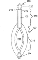
Figure 16 is used on patient skin forming and the axonometric chart of the surgery closing device 100 of closed given shape wound.The simple mechanism that is used on patient skin forming with closed given shape wound is useful at multiple conventional medical operating, comprises the tuberosity biopsy or removes dermatosis and the unnecessary skin of removal in bariatric surgery or cosmetic surgery.The surgery closing device 100 of Figure 16 is similar to previous embodiment very much, except between first bonding sheet 102 that limits the wound shape and second bonding sheet 104, non-linear opening 200 being arranged.One especially in the preferred embodiment, given shape opening 200 has the rhombohedral geometry of round end, and some is as rugby or lenticular lens.First track 112 and second track 114 meet the profile of given shape opening 200.Preferably, first and second bonding sheets 102,104 link together outside the end of given shape opening 200.Alternatively, can be with opening 200 towards open position or make position biasing.The shape that keeps opening 200 when removable given shape insert 202 is used in surgery closing device 100 is attached to patient skin.If towards the make position biasing, then this is even more important with given shape opening 200.Removable given shape insert 202 also can be used as the guiding piece of dissecting knife with the medial cuts skin around given shape opening 200, or can before forming wound, remove given shape insert 202.Figure 17 illustrates the surgery closing device 100 of the Figure 16 that removes given shape insert 202.The edge of given shape opening 200 preferably tilts with an angle (normally 45-90 degree), dissecting knife is remained on suitable angle cuts out wedge shape skin nodules sample with auxiliary.
Figure 18 illustrates and applies the surgery closing device 100 of conjunction 106 with Figure 16 of closed wound.Figure 19 illustrates the surgery closing device 100 of the in place and Figure 16 that is in the close position of conjunction 106.
Remove big dermatosis for the surgery closing device 100 that uses Figure 16, must remedy significant skin defect, thereby can make the skin adjacent circumferential expansion ideally to given shape opening 200.But orthopaedic surgical operations closing device 100 belows and in skin, form the little otch of certain pattern on every side, thus skin stretches with lattice, and this lattice can heal to cover skin defect.Can provide the isolated plant of small-sized skin blade to carry out this task with required pattern.Can use inflatable utricule or other analog before biopsy or excision pathological changes, to make skin expansion remedy skin defect.
Figure 20 is another embodiment that is used on patient skin, forming the surgery closing device 100 of given shape wound.Surgery closing device 100 has the given shape opening 200 that limits the wound shape between first bonding sheet 102 and second bonding sheet 104.The shape that keeps opening 200 when removable given shape insert 202 is used in surgery closing device 100 is attached to patient skin.First track 112 and second track 114 meet the profile of given shape opening 200.
Shown in the cutaway view among Figure 22, first inner chamber, 204 longitudinal extensions pass first track 112, and second inner chamber, 206 longitudinal extensions pass first branch 210 and second branch 212 of second track 114 to admit crestal line 208 respectively.Figure 23 illustrates the cutaway view of first and second tracks 112,114 of the surgery closing device 100 of wire forming spare 208 and conjunction 106 Figure 20 in place.After first inner chamber 204 and second inner chamber 206 are passed in insertion; The end of first branch 210 and second branch 212 links together; For example link together, be positioned at second bending section 220 of wire forming spare 208 other ends with formation, shown in Figure 24 and 25 through welding, brazing or soldering.First and second bending sections 214,220 preferably shape are arranged to form lug or handle so that grasp.
Figure 24 illustrates the surgery closing device 100 that assembles fully that is shown in an open position.Wire forming spare 208 is positioned to outwardly-bent, and first branch 210 and second branch 212 open part 216 around given shape opening 200, will install 100 thus and setover towards open position.Alternatively, conjunction 106 may be attached to wire forming spare 208, thereby locatees around the closing section 218 of wire forming spare 208.
Figure 25 illustrates the surgery closing device 100 shown in Figure 24 that is in the close position.Wire forming spare 208 is the position of longitudinal sliding motion to the straight closing section of first branch 210 and second branch 212 218 around given shape opening 200, will install 100 thus and setover towards make position.Because conjunction 106 is attached to wire forming spare 208, so conjunction 106 can slide on first and second tracks 112,114 so that surgery closing device 100 is fixed on make position automatically.Perhaps, can apply conjunction 106 in the step separately.As another alternative form, wire forming spare 208 can be configured to enough rigidity so that surgery closing device 100 is remained on make position and need not conjunction 106.
Alternatively, but the part 216 orthopaedic surgical operations closing devices 100 of opening of wire forming spare 208 prune away after being in the close position or break off.Alternatively, can be before cutting wire forming spare 208 be applied clip, bail or other securing member to prevent that first branch 210 and second branch 212 from expanding when opening part 216 and open removing.
In alternate configuration, wire forming spare 208 can be by processing such as the ductile material of annealed aluminium or copper, thereby surgery closing device 100 can manually form and opens or closes the position.In addition, ductility wire forming spare 208 can be used for forming surgery closing device 100 with adaptive non-rectilinear wound or the wound that is pre-existing in.
Figure 26 is used to apply continue closing force to promote the sketch map of the surgery closing device 230 that big skin wounds heals.After removing strip biopsy sample or big dermatosis, have and to carry out the remarkable skin defect that wound heals fully and need remedy before.Long-term or successive closing force can help lend some impetus to the closed and healing of wound.The very pliable and tough and deflection bonding sheet 234 that the middle part is had opening 236 is applied to patient skin around wound or pathological changes.How arrow 232 indicating closing power are applied to bonding sheet 234 to promote wound closed around opening 236.
Figure 27 A, 27B and 27C illustrate and are used to apply the various structures of executing draw piece 240 that continue closing force in the surgery closing device 230 of Figure 26.Figure 27 A illustrates and executes draw piece 240, and this is executed draw piece 240 and has the slender bodies 248 that has barb 246 along the both sides of executing draw piece 240.First end of executing draw piece 240 is attached to anchoring piece 242, and this anchoring piece 242 for good and all or be removably attached to bonding sheet 234.The slender bodies 248 of executing draw piece 240 passes clamp 244, and this clamp 244 also for good and all or be removably attached to bonding sheet 234.Clamp 244 is assisted to be equipped with barb 248 along the both sides of executing draw piece 240 and is formed for optionally straining the ratch mechanism type of executing draw piece 240.Execute the slender bodies 248 of draw piece 240 and preferably processed by elastomeric material, this material will provide the pulling force of required scope.Figure 27 B executes the draw piece of executing that draw piece 240 is similar to Figure 27 A, except barb 246 by 250 replacing along having executed the bulge of draw piece 240 both sides or having lumpd.The draw piece 240 of executing of Figure 27 C has and clamp 244 interactional waveforms or corrugated part 252, to form the pulling force governor motion.Waveform or corrugated part 252 also become spring part with elongate articles 248, so ripple slender bodies 248 can be made up of tinsel or the lower polymer of amount of deflection, with substituting as elastomeric material among other embodiment.Waveform or corrugated part 252 can be smooth or they can form spiral or other 3D shape.
Figure 28 illustrates the surgery closing device 230 that is configured to apply unidirectional closing force.A plurality of execute opening 236 that draw piece 240 crosses over bonding sheets 234 each other almost parallel arrange.Each pulling force of executing in the draw piece 240 can be regulated separately.
Figure 29 illustrates the surgery closing device 230 that is configured to apply radial occlusive force.A plurality ofly execute the center of opening 236 that draw piece 240 roughly crosses bonding sheet 234 from public attachment point 254 radiation.Perhaps, a plurality of draw pieces 240 of executing can be crossed over the diameter of the opening 236 of bonding sheet 234 and arrange.Each pulling force of executing in the draw piece 240 can be regulated separately.
Figure 30 illustrates and is at random or the surgery closing device 230 of executing draw piece 240 of particular configuration.This layout is for being useful for irregularly shaped wound or pathological changes customization surgery closing device 230.Each anchoring piece 242 and the position of clamp 244 and the pulling force that each is executed in the draw piece 240 can be regulated separately.
Figure 31 illustrates permission applies pulling force 240 with any required pattern surgery closing device 230.Deflection bonding sheet 234 is configured such that executing draw piece 240 can be attached on the surface of bonding sheet 234 at any point easily.
Figure 32 is the detail drawing of an embodiment of the surgery closing device 230 of Figure 31, and wherein the surface of bonding sheet 234 is made up of mesh material 256.The draw piece 240 executed with barb 250 inserts and passes mesh material 256 and tensioning applies pulling force with desired form to surgery closing device 230.Mesh material 256 has the function of above-mentioned anchoring piece 242 and/or clamp 244.
Figure 33 is the detail drawing of another embodiment of the surgery closing device 230 of Figure 31, and wherein bonding sheet 234 is configured with a plurality of rings 258 in its surface.Execute draw piece 240 insert pass respectively encircle 258 and tensioning with desired form surgery closing device 230 is applied pulling force.Each encircles 258 and has the function of above-mentioned anchoring piece 242 and/or clamp 244.
Figure 34 illustrates and is used for the attached surgery closing device 260 of executing the independent bar shaped bonding sheet 262,264 of draw piece 240.Anchoring piece 242 is attached to first bonding sheet 262, and clamp 244 is attached to second bonding sheet 264.This allows to arrange the bigger motility of executing draw piece 240 with any desired form.
Figure 35 illustrates the surgery closing device 260 of three Figure 34 that are applied to the patient.In this example, execute the roughly parallel layout of draw piece 240, so that unidirectional closing force to be provided.Also maybe be by multiple other pattern.
Figure 36 illustrate utilize constant force spring 270 and anchoring piece 242 execute draw piece 240.Constant force spring 270 has spring, and how how displacement all provides the roughly advantage of constant force.Therefore, when wound begins closed and heals, need not to regulate again the pulling force of executing in the draw piece 240.
What Figure 37 illustrated constant force spring 270 withdrawal executes draw piece 240.Hook 272 is attached in the end of constant force spring 270.Figure 38 illustrates that constant force spring 270 stretches executes draw piece 240.Hook 272 passes ring 274 and hooks, and ring 274 may be attached to anchoring piece or directly is attached to bonding sheet.
Figure 39 illustrates the multidirectional draw piece 280 of executing that utilizes Wind spring axle 282.A plurality ofly radially execute draw piece 284 radially extends and be connected to same quantity from Wind spring axle 272 anchoring piece 286.
In some cases, the extruding that advantageously after closure, wound is applied controlled quatity is to promote healing.Figure 40 A, 40B and 40C illustrate the surgery closing device 100 that is configured to wound is applied the scalable extruding.Figure 40 A illustrates the cutaway view of the surgery closing device 100 that is applied to patient skin.Surgery closing device 100 comprises first bonding sheet 102, second bonding sheet 104 and first passage shape conjunction 106, and this first passage shape conjunction 106 is configured to be enclosed within slide on first and second rail bars or the track 112,114 has controlled width gap 103 therebetween so that first and second bonding sheets 102,104 are kept together, make.
Between first bonding sheet 102 and second bonding sheet 104, form wound, and open this wound and carry out surgical operation, shown in Figure 40 B.Should be pointed out that the edge of edge extend past first and second tracks 112,114 of wound.
Figure 40 C illustrates with the wound after surgery closing device 100 closures.Second channel shape conjunction 107 has slided on first and second tracks 112,114 so that first and second bonding sheets 102,104 are kept together.The channel width of second channel shape conjunction 107 is less than the channel width of first passage shape conjunction 106, and this forms the extruding of controlled quatity at wound line place.
Figure 41 illustrates first and second bonding sheets, 102,104 distinct surgery closing devices 100 when being shown in an open position.When the very large surgery passage of needs underwent surgery, this structure was favourable.Can comprise that labelling, pallet or other aligning guide guarantee the correct aligning and the butt joint of period of contact wound.
Figure 42 illustrates the surgery closing device 100 of first and second bonding sheets 102,104 permanent attachment at two ends.The advantage of this structure is that when wound is closed, wound will be aimed at correct butt joint automatically.Perhaps, but an only end permanent attachment of first and second bonding sheets 102,104.
Figure 43 illustrates the surgery closing device 100 of conjunction 106 to promote that device is closed of band Y shape end 109.The conical entrance of the Y shape end 109 on the conjunction 106 reduces to apply the required power of conjunction 106 closed wounds.
Figure 44 illustrates conjunction 111 and is configured to the surgery closing device 100 of closing device in succession.This structure is convenient to implement method mentioned above among Figure 40 A, 40B and the 40C through first conjunction 106 and second conjunction 107 are integrated into single parts.Alternatively, conjunction 111 can have taper Y shape end 109, and embodiment as discussed previously is such.After accomplishing surgical operation, slide on first and second tracks 112,114 and then second narrower part 115 of conjunction is slided on first and second tracks 112,114 and closed wound through first 113 with conjunction.Second narrower part 115 of conjunction can be configured to after closure wound is provided the extruding of controlled quatity.
Figure 45 illustrates first and second conjunctions 117,119 and is configured to the surgery closing device 100 of closing device in succession.Second conjunction, 119 to the first conjunctions 117 are narrow.Through first conjunction 117 is slided on first and second tracks 112,114 from an end, when first conjunction 117 is withdrawed from, the second narrower conjunction 119 is slided into first and second tracks 112,114 then and come closed in succession surgery closing device 100 from the opposite end.Closed in succession advantage is to reduce power and shearing force through closed surgery closing device 100 progressively.Can use a plurality of steps, comprise the conjunction that passage is also wideer than first conjunction alternatively.
Figure 46 is that conjunction 106 has the cutaway view that is used for the surgery closing device 100 of first and second tracks, 112,114 accurate isolated middle ridge 101.Method mentioned above is favourable to this structure among Figure 40 A, 40B and the 40C for implementing, because it keeps first and second tracks 112,114 carefully to aim at, controlled gap 103 is arranged therebetween.
Figure 47 is that conjunction 106 has the cutaway view of surgery closing device 100 that is used for wound is applied first passage 121 and the narrower second channel 123 of scalable extruding.Method mentioned above is favourable to this structure among Figure 40 A, 40B and the 40C for implementing.Can at first this surgery closing device 100 be applied to the patient, make first passage 121 be positioned at first and second tracks, 112,114 tops.After accomplishing operation, can apply conjunction 106 again, make narrower second channel 123 be positioned at first and second tracks, 112,114 tops wound is applied the extruding of controlled quatity.
Figure 48 is the cutaway view that 106 conjunctions are integrated into the surgery closing device 100 of one of bonding sheet.With previous embodiments, conjunction 106 has first passage 121 and the narrower second channel 123 that is used for wound is applied the scalable extruding.Also has multiple channel width.The closure of surgery closing device 100 need be mentioned conjunction 106 a little to place it on the opposite side on the single track 114.
Figure 50-54 is to use extruding rather than pulling force to apply the embodiment that long-term or continuous closing force is assisted the surgery closing device 300 that promotes that wound is closed and heal.This is particularly useful for the removal part skin of big wound and/or for example tuberosity biopsy and the wound of tissue.Figure 50 is the assembly drawing of surgery closing device 300.Surgery closing device 300 has two major parts: bonding sheet 302 and keeper 304, bonding sheet 302 is attached to patient skin, when keeper 304 is used to be in application to patient skin bonding sheet 302 is remained on squeezed state.
Figure 52 illustrates the enlarged drawing of the example constructions of expansion cell 310.The arcuate rib 318 of a plurality of circumferential orientation is attached to bonding sheet 302 on the both sides of opening 306.There are a plurality of extrusion spring spares 320 location between each rib 318, and these extrusion spring spares 320 are biased to pushes adjacent rib 318 open.Because 308 opposings of perimembranous ring stretch, so the clean effect of extrusion spring spare 320 is towards the make position pushing, shown in arrow 316 with central opening 306.Extrusion spring spare 320 can be the metal extrusion spring; For example rustless steel or Ni-Ti alloy elasticity extrusion spring spare, for example rubber, neoprene, chloroprene rubber (Santoprene), ethylene vinyl acetate etc. or the elastic foam extrusion spring spare processed by elastomer or other elastomeric polymer.Figure 52 illustrates only a kind of in multiple possibly structure of expansion cell 310.
Figure 53 illustrates the half the cut away view that keeper 304 is assembled to the surgery closing device 300 of bonding sheet 302.Keeper 304 have with bonding sheet 302 on a plurality of grooves 322 of each arcuate rib 318 interlocking so that bonding sheet 302 is remained on expanding position, make extrusion spring spare 302 be in squeezed state.Keeper 304 is preferably formed by the molded of polymeric material that rigidity is enough to resist the combining ability of extrusion spring spare 320.
The surgery closing device 300 that assembles shown in figure 50 is bonded to patient skin, makes central opening 306 surrounding target wound site location.The inward flange of keeper 304 can be used as and is used to the guide portion of cutting the wedge biopsy sample or waiting to remove the part of pathological tissues.When needs closure wound, keeper 304 is lifted away from bonding sheet 302, shown in the cut away view of Figure 54, stay the bonding sheet 302 that is bonded to skin, shown in Figure 51.Rib 318 on the bonding sheet 302 no longer receives the restriction of groove 322 on the keeper 304, so extrusion spring spare 320 pushes central opening 306 towards make position.
In the one optional structure of orthopaedic surgical operations closing device 300, extrusion spring spare 320 and/or bonding sheet 302 can be by central opening 306 is slowly processed towards the viscoelastic material of make position pushing.Alternatively, viscoelastic material can be through patient's body heat activation.
Figure 55 illustrates the apolegamy structure of any embodiment of the surgery closing device 300 that can be used for Figure 50-54 or surgery closing device described herein.Surgery closing device 300 is configured with on-plane surface or the three-D profile that is used to be engaged to body part.In the example shown, surgery closing device 300 shapes are as dome shaped, to cooperate other convexly curved part of patient's scalp or health better.Also has other structure.
Figure 56-58 illustrates another apolegamy structure of any embodiment of the surgery closing device 300 that can be used for Figure 50-54 or surgery closing device described herein.Surgery closing device 300 comprises skin cutter 330, and this skin cutter 330 has a plurality of cutting blades 332 that are attached to handle 334.What Figure 56 and 57 illustrated surgery closing device 300 with skin cutter 330 overlooks and looks up exploded view.Skin cutter 300 is fitted in surgery closing device 300 over top, makes cutting blade 332 extend through the break-through groove on bonding sheet 302 and the keeper 304.The surface extension of bonding sheet 302 is passed than short distance in the tip 336 of cutting blade 332, and shown in the assembly drawing of Figure 58, about 1-2mm is dark thereby they can cut skin.Preferably, cutting blade 332 is arranged to them will cut skin with mesh pattern around wound, thereby skin is extensible to remedy owing to removing the skin defect that a part of skin and below tissue form.Little otch can heal sooner, stays the cicatrix that lacks than big wound in the removal lesions.After transdermal, remove skin cutter 300.
Figure 59 and 60 illustrates the apolegamy structure that can be used for any embodiment of surgery closing device described herein.Figure 59 is the axonometric chart with surgery closing device 340 of segmentation track 342,344, and segmentation track 342,344 is convenient to withdraw wound to improve the wound path.Each track 342,344 is configured with through elastic rope 348 etc. and is linked at together a plurality of sections 346.When wound and surgery closing device for example through using one or more surgery traction apparatuss 340 when standing withdrawal force, each section opened in 346 minutes, as forming gap 350 between each section that Figure 59 is shown in 346.Figure 60 is the enlarged drawing that the segmentation track 342,344 of gap 350 visible elastic ropes 348 was opened and passed through to each section in 346 minutes.The elasticity of bonding sheet 352 allows it when wound is withdrawn, to stretch.
When unclamping withdrawal force, elastic rope 348 retracts its normal structure continuously with segmentation track 342,344, is similar to structure shown in Figure 17.When wanting closed surgical wound, can apply conjunction 106, shown in Figure 18 and 19.
Figure 61 illustrates another apolegamy characteristic of any embodiment that can be used for surgery closing device described herein, comprises Figure 59 and 60 illustrated embodiments.Figure 61 is the axonometric chart that the surgery closing device 360 of lateral slot 362 is arranged on bonding sheet 364.Bonding sheet 364 stretched when lateral slot 362 allowed to apply withdrawal force.Lateral slot 362 also allows bonding sheet 364 to meet the make position of surgery closing device, and is shown in figure 19.Because lateral slot 362, the less amount of deflection of bonding sheet 364 material requires adapts to the withdrawal of surgery closing device 360 or the change of shape of period of contact with distortion.
Another apolegamy characteristic that can be used for any embodiment of surgery closing device described herein is that surgery closing device 100 is configured with one or more hot switching paths so that cold water or other heat-exchange fluid circulation pain management and inflammation when helping at wound healing in first and second bonding sheets 102,104.These hot switching paths pattern or other structure that can wriggle is arranged to improve heat exchanger effectiveness.Surgery closing device 100 can have the port that is used for hot switching path is connected to external pump.Perhaps, can combine surgery closing device 100 to use other heat-exchange devices to raise or reduce the temperature of wound site.
Figure 62-65 illustrates and is configured on patient skin to form and another embodiment of the surgery closing device 400 of closed given shape wound, for example wedge biopsy wound.Surgery closing device 400 is similar to the embodiment of Figure 16 in many aspects.The non-rectilinear given shape opening 408 that limits the wound shape is arranged between first bonding sheet 402 and second bonding sheet 404.One especially in the preferred embodiment, given shape opening 408 has ellipse or the rhombohedral geometry of round end, and some is as rugby or biconvex lens.First track 412 and second track 414 meet the profile of given shape opening 408.Preferably, first and second bonding sheets 402,404 link together outside the end of given shape opening 408.First bonding sheet 402, second bonding sheet 404, first track 412 and second track 414 are processed by the deflection material, and this deflection material allows given shape opening 408 to move to make position from open position.Alternatively, can be with given shape opening 408 towards open position or make position biasing.
During use, the attached of surgery closing device 400 has first bonding sheet 402 and second bonding sheet 404 of opening conjunction 406 to be bonded to patient skin, given shape opening 408,420 located, around pathological changes to be checked shown in Figure 62.Form wound with dissecting knife 424 or other cutting appliance, use the inclination inward flange 422 of opening the given shape opening 420 on the conjunction 406 as the cutting guide portion, shown in Figure 63.Another advantage that opening conjunction 406 provides is, its protection surgery closing device 400 during cutting step, avoid accidental cutting with given shape opening 408 adjacent edges.Shown in Figure 64, remove the cut-out of tissue, and be lifted away from track 412,414 and remove and open conjunction 406 through opening conjunction 406.Through passage 426,428 being slided on the track 412,414 and closed conjunction 410 is attached to the wound on surgery closing device 400 closed given shape openings 408 and the skin, shown in Figure 65.Alternatively, device 400 can be configured to wound applied when promote healing when attached closed conjunction 410 extruding of aequum.
Figure 67-the 71st is configured on the closed patient skin embodiment of the surgery closing device 440 of big wound.An instance can benefiting from the operation of using this device is after successfully carrying out bariatric surgery, to remove redundant skin.Surpass 200,000 bariatric surgeries every year at present, and quantity is increasing also.Removing redundant skin is operation very consuming time, on by the straight line of anatomic landmark guiding at predictable location 2,000 pins of having an appointment.In order to make this operation carry out sooner, this operation is undertaken by the surgeon of a team usually.Figure 66 A-66D illustrates and is generally used for the wound line that orthopaedic surgical operations is removed redundant skin.
Figure 67 illustrates the surgery closing device 440 that is shown in an open position.This surgery closing device 440 can be around the single assembly of patient's entire circumference or alternatively this device can be modular, and form by each that separate or interconnected section.Surgery closing device 440 has first track 442 and second track 444, bonds them to patient skin with contact binding agent backing.In a preferred embodiment, first track 442 is the same with wound length with second track 444 long or longer slightly than wound length.After bariatric surgery, remove under the situation of redundant skin, but first track 442 and second track, 444 long enoughs are with fully around the patient.Perhaps, first track 442 and second track 444 can be can be bonded to patient skin and end to end banded each shorter section when closed wound.Alternatively, first end of first track 442 and second track 444 can for good and all link together so that the closure of installing.
Figure 68 illustrates the surgery closing device 440 of the Figure 67 that is shown in an open position and is bonded to patient's abdominal part.First track 442 and second track 444 are placed along target wound line, make the unnecessary skin that will remove between first track 442 and second track 444.Figure 69 illustrates the patient who has excised redundant skin and fascia.The little edge that stays film is attached to use conventional sewing method to carry out.
Figure 70 illustrates the surgery closing device 440 that is in the part make position, makes first track 442 and second track 444 close to each other, thus make skin edge suitably near.Conjunction 446 begins on first end of first track 442 and second track 444.Figure 71 illustrates the surgery closing device 440 on the patient's abdominal part that is in the part make position.
Figure 72 illustrates the surgery closing device 440 on the patient's abdominal part that is in complete make position.Conjunction 446 has slided on first track 442 and second track 444.Alternatively, can remove the unnecessary length of first track 442 and second track 444.
Figure 73 A-73E illustrate can with the apolegamy characteristic of the surgery closing device 440 shown in Figure 67-72 or any other surgery closing device combination as herein described.Figure 73 A illustrates first track 442 that is bonded to patient skin and the short sample part of second track 444.After the unnecessary tissue of excision, insert the preparatory formation hole of passing in first track 442 and second track 444 450 with aiming at rope 448.Then, tractive is aimed at rope 448 so that first track 442 and second track 444 are close to each other.Alternatively, aim at rope 448 and can have barb, ratchet or further feature first track 442 and second track 444 are locked together in this position.Then conjunction 446 being slided into should closure to fix on first track 442 and second track 444.Alternatively, can remove the unnecessary length of aiming at rope 448 this moment.Figure 74 is the enlarged drawing of the surgery closing device 440 of Figure 73 A-73E of being in the close position.
Other surgical operation than big wound or any wound that need possibly stay obvious cicatrix also can be benefited from the use of this device, comprises laparotomy ventrotomy, thoracotomy, cesarotomy, the art of having a shave and breast implant surgery.
Such as one of challenge of removing the big wound of closure that runs into during the redundant skin of obese patient is the pleat angle (" dog ears ") that prevents in the closed wound.When a side of wound longer or the pleat angle can occur during unexpected stretching during at closed wound when a side of wound than opposite side.If in butt joint and the additional length of not noting guaranteeing longer side during sewing up along the shorter side uniform distribution, skin can and fold out the shape of similar dog ears sometimes along the side protuberance of wound.For good cosmetic result, must remove sew up and sew up wound again.It can be very time-consuming for the surgeon, correcting this mistake.
Surgery closing device of the present invention can help to prevent the generation at pleat angle very much.A kind of method is that the track of surgery closing device is made multistage along the one or both sides of closure.Can push along the space between each section of the longer side of wound with additional length that skin is provided during docking uniform distribution along shorter side.Rope for traction mentioned above can be used for guaranteeing the even butt joint between the device period of contact wound both sides.Alternatively or additionally, vertical rope for traction can be set along the one or both sides of surgery closing device.But the vertical rope for traction on the longer side of tractive wound is to shorten before the longer side of wound equably in device butt joint and closure.Alternatively, can make than each section weak point on the shorter side, so that evenly butt joint along each section of the longer side of wound.Be the skin on the intentional stretching wound shorter side before the bonding sheet with the surgery closing device is applied to patient skin on the other hand.The even butt joint and the closure of wound when this can guarantee that conjunction is applied to the surgery closing device.
The surgery closing device can be made one or more standard constructions based on conventional wound geometry.Perhaps, can be based on each patient's sized surgery closing device.
Figure 75 illustrates the low profile embodiment that the patient wears more comfortable and more unconspicuous surgery closing device 460.Surgery closing device 460 has first bonding sheet 462 and second bonding sheet, 464, the first bonding sheets 462 are attached that first track 472 is arranged, and second bonding sheet 464 is attached second track 474 is arranged.Alternatively, as shown in the figure, the end that first and second bonding sheets 462,464 can surpass track 472,474 links together.Preferably, bonding sheet 462,464 can be processed by gas-pervious deflection material, and such as deflection fabric or (reinforcing alternatively) perforation deflection polymer sheet, downside is applied with the contact binding agent.Alternatively, hydrophobic material processed or be coated with to first and second bonding sheets 462,464 can to prevent by patient's blood absorption or pollution by hydrophobic material.Flexible conjunction 466 sizes and structure are arranged to slide on the track 472,474 so that first bonding sheet 462 and second bonding sheet 464 are combined.
Figure 76 illustrates the cutaway view of the low profile surgery closing device 460 shown in Figure 75.Between first track 472 and second track 474, limit wound plane 468.Alternatively; Surgery closing device 460 can be to pass first and second bonding sheets 402,468 well cuttings of the cutting planes between 404; Perhaps surgery closing device 460 can be intact, thereby the surgeon will cut when forming skin wounds and wear surgery closing device 460.Perhaps, surgery closing device 460 can be bored a hole at 468 places, wound plane or partly cut and wear.First track 472 and second track 474 preferably take the shape of the letter U or J-shaped cross section and to be positioned to its end adjacent with wound plane 468.Preferably, first track 472 and second track 474 are processed by for example stainless metal, and have been cut with or etching has the groove 470 of certain pattern, so that its deflection, keep the intensity of U-shaped or J-shaped structure simultaneously.The instance of possible groove 470 geometries is shown with close up view among Figure 77,78 and 79.The preferably c-shaped cross section of deflection conjunction 466 is with closely equipped around first track 472 and second track 474.Preferably, deflection conjunction 466 is processed by for example stainless metal, and cut or groove 476 that etching has certain pattern so that its deflection, keep the intensity of C shape structure simultaneously.The instance of possible groove 476 geometries is shown with close up view among Figure 78 and 79.Alternatively, deflection conjunction 466 can cover or scribble the deflection polymer of low-friction coefficient.Alternatively, deflection conjunction 466 can have the minimum disengagement lever 478 of profile that can after conjunction 466 is installed, remove so that install 460.
Figure 78 illustrates the apolegamy structure of the low profile surgery closing device 460 shown in Figure 75.The end of track 472,474 and/or the end of deflection conjunction 466 can be formed with conical configuration so that track 472,474 inserts in the conjunction 466.
Figure 79-80 illustrates another apolegamy structure of the low profile surgery closing device 460 shown in Figure 75.Track 472,474 and deflection conjunction 466 can be formed with interlocking structure, in case conjunction 466 installs, this interlocking structure can be locked to track 472,474 securely with conjunction 466.In the example shown, interlocking structure comprises a pair of lug 480 that is formed on deflection conjunction 466 ends, and this is to a pair of spring catcher 482 interlockings on lug 480 and the end that is formed on track 472,474.
Figure 81-86 illustrates another low profile embodiment of surgery closing device 490.Shown in Figure 82, surgery closing device 490 has first bonding sheet 492 and second bonding sheet 494 of joining along the opening that limits the wound line 493.First bonding sheet 492 and second bonding sheet 494 can separate, and the end that perhaps can surpass opening 493 alternatively links together.First sleeve 496 is connected to first bonding sheet 492 along the one edge of opening 493, and second sleeve 498 is connected to second bonding sheet 494 along the opposite edges of opening 493.Preferably, first bonding sheet 492, first sleeve 496, second bonding sheet 494 and second sleeve 498 are processed by the airy fabric of deflection.Can form through binding agent bonding, stitching or welding fabric with the sleeve shown in the cutaway view 496,498 among Figure 83.Sleeve 496,498 can be as shown in the figure successive, and perhaps they can be configured to intermittently each section so that surgery closing device 490 more has flexible.
The sleeve 496,498 of surgery closing device 490 is identical with track function among other embodiment described herein.The function of conjunction is implemented by elongated fork-shaped conjunction 500 shown in Figure 84, has the first fork part 502 and second that being configured to slides respectively is fitted in first and second sleeves 496,498 and pitches part 504.The first fork part 502 of fork-shaped conjunction 500 and the second fork part 504 are at one end attached through lateral member 503.Fork-shaped conjunction 500 preferably by rustless steel, Ni-Ti or other suitable alloy through processing such as any suitable technology of machined, punching press, photoetch etc.Perhaps, fork-shaped conjunction 500 can be processed by rigid polymer or fiber reinforced polymer composites.One especially in the preferred embodiment; Fork-shaped conjunction 500 is configured with the part and opens part 506 and closing section 508; Open part 506 first fork parts 502 and the second fork part, 504 spaced apart less gaps 505 in the part; Pitch part 504 side by side at closing section 508, the first fork parts 502 and second, have little or no the gap therebetween.In addition, have end sections 507, tapered at end sections 507, the first fork parts 502 and the second fork part 504 so that insert first and second sleeves 496,498.Alternatively, has the covering sealing member 510 that is attached to fork-shaped conjunction 500.This covering sealing member 510 can be by processing with fork-shaped conjunction 500 identical materials or different materials.
During use, surgery closing device 490 usefulness first bonding sheet 492 is bonded to patient skin with the binding agent that contacts on second bonding sheet, 494 downsides.The closing section 508 of fork-shaped conjunction 500 is positioned in first and second sleeves 496,498 so that surgery closing device 490 is remained on make position, shown in Figure 81.Then, with 500 longitudinal sliding motions of fork-shaped conjunction, thereby the part of fork-shaped conjunction 500 is opened part 506 and is positioned in first and second sleeve 496,498 and partially opens the position so that surgery closing device 490 is remained on.When orthopaedic surgical operations closing device 490 is in a partly opened position, on skin, form wound through the opening 493 that is formed between first bonding sheet 492 and second bonding sheet 494.After forming wound, can temporarily fork-shaped conjunction 500 be removed to allow opening 493 and below retraction of tissue to undergo surgery through wound from first and second sleeves 496,498.After accomplishing operation, fork-shaped conjunction 500 is inserted and move to make position again come the opening 493 between closed first bonding sheet 492 and second bonding sheet 494.This tissue will with the operation before identical position accurate butt-joint.Alternatively, fork-shaped conjunction 500 can apply extruding force in make position on wound.The each several part 506,507 that no longer needs of fork-shaped conjunction 500 preferably through pitch that part 502,504 is bent upwards and score place on fork part 502,504 downsides breaks off and removing, perhaps alternatively removes through pitching part 502,504 with cut.Then, be folded on the closing section of first and second sleeves 496,498 and fork-shaped conjunction 500 covering sealing member 510, and with 490 lockings of surgery closing device be sealed in make position, shown in Figure 85-86.Alternatively, cover sealing member 510 can have with the first and second fork parts 502,504 in the pair of locking pins 512 of pair of holes 514 interlockings so that fork-shaped conjunction 500 is fixed on make position.
Alternatively or additionally, cover sealing member 510 and can have the contact binding agent with 490 lockings of surgery closing device be sealed in make position.
Figure 87 illustrates the apolegamy wound template 590 of the surgery closing device 490 that can be used for Figure 81-86.Wound template 590 is fitted on the surgery closing device 490 when surgery closing device 490 is in closure or partially opens the position.Central channel 592 has and extends in the opening 493 to the lip that extends below 594, is switched to when the formation wound to protect first sleeve 496 and second sleeve 498.Wound template 590 is preferably processed by the rigidity of dissecting knife or other cut or semi-rigid polymer or metal by opposing.Wound template 590 also is suitable for other embodiment of surgery closing device described herein.
Figure 88 illustrates the modification of fork-shaped conjunction 500, the modification of this fork-shaped conjunction 500 have the fork part to projecting inward arc or arcuate curvature, thereby when fork-shaped conjunction 500 is locked in make position, in wound, apply the clossing pressure of increase in the heart.
Figure 89 illustrates the modification of fork-shaped conjunction 500, and its function class is similar to the part of the conjunction of fork-shaped shown in Figure 84 500 and opens part 506.This modification of fork-shaped conjunction 500 fork part 502, between 504 gapped 505 with to the opening on the surgery closing device 490 493 and following side skin is applied expansion force form otch so that pass opening 493.
Figure 90 illustrates the modification that is configured to when surgery closing device 490 is in the close position to promote with the fork-shaped conjunction 500 of wound adjacent tissue.The first fork part 502 and the second fork part 504 are upwards angled, thereby when fork-shaped conjunction 500 inserts first sleeve 496 and second sleeve 498, promote the tissue adjacent with wound.Promote the sagging or withdrawal that the tissue adjacent with wound is used to reduce the tissue that during agglutination, takes place usually.This can reduce cicatrization and improve outward appearance.Similarly, the conjunction of other type as herein described also can be configured to when the surgery closing device is in the close position, promote the tissue adjacent with wound.
Figure 91 illustrates another apolegamy structure that when the surgery closing device is in the close position, can be used for promoting the tissue adjacent with wound.Binding agent protection covering 600 with tent like structure 602 can apply to promote the tissue adjacent with wound along the wound line.Tent like structure 602 can be processed by polymer or metal that rigidity is enough to promote the tissue adjacent with wound.Protection covering 600 can apply when wound is closed or can begin to heal after-applied after a while.For example, in case begun healing, removable conjunction also can be applied to protection covering 600 on the surgery closing device.Alternatively, tent like structure 602 can be processed by elastomeric material, and this elasticity is enough to make it can be flattened to use the contact binding agent that it is applied on the surgery closing device.Then, when unclamping, the tissue that the elastic restoring force of tent like structure 602 will be adjacent with wound promotes.
Figure 92,93 and 94 illustrates another modification of the surgery closing device 490 of Figure 81-86, and it utilizes the first and second fork-shaped conjunctions 500,501 that insert from first and second sleeves, 496,498 opposite ends so that surgery closing device 490 is remained on make position.Figure 92 is illustrated in and inserts the first and second fork-shaped conjunctions 500,501 surgery closing device 490 before, and Figure 93 illustrates the surgery closing device 490 that is in the close position after the insertion first and second fork-shaped conjunctions 500,501.Use two fork-shaped conjunctions 500,501 added security to be provided for the surgery closing device 490 that is in the close position.Alternatively, the first and second fork-shaped conjunctions 500,501 can the telescopically matched together, shown in Figure 94, and/or can have latch-up structure so that the first and second fork-shaped conjunctions 500,501 are locked together.
The first and second fork-shaped conjunctions 500,501 also can be used for for surgery closing device 490 customizable length being provided.First bonding sheet 492 and second bonding sheet 494 can cut into Len req to adapt to target otch or existing otch or wound.The cut end that can the fork-shaped conjunction 500 of suitable length be inserted sleeve 496,498 keeps together with the cut end with opening 493.If desired, the first and second fork-shaped conjunctions 500,501 can have different length.For example, the first very short fork-shaped conjunction 500 can just be long enough to before the cut end and the opening 493 of sleeve 496,498 kept together with closed wound in 501 insertions of the second fork-shaped conjunction.
Figure 95-96 illustrates the additional structure that can be used for Figure 81-86 Chinese and foreign department closing device 490.Medicine injects collector 520 and has the person in charge 516, and the person in charge 516 has the nearside connector 522 and closed distal end 517 such as the accessory of Rule.At least one, preferably several medicines inject pins or conduit 518 and are connected to and are responsible for 516.Shown in exploded view among Figure 95, fork-shaped conjunction 500 has medicine when allowing orthopaedic surgical operations closing device 490 to be in the close position and injects a series of holes 524 that pin or conduit 518 insert wounds.Figure 96 also illustrates fork-shaped conjunction 500 can be shortened, thereby it only comprises that closing section 506 and apolegamy ground comprise tapering point part 507.Alternatively, medicine injection collector 520 can comprise that also contact binding agent and/or stop pin or other latch-up structure are to seal and to be fixed on make position with surgery closing device 490.When wound is still opened or orthopaedic surgical operations closing device 490 can insert medicine after closed and inject collector 520, shown in Figure 96.
Figure 97 illustrates another modification that medicine injects collector 520, and its Chinese medicine injects pin or conduit 518 replaces left and bending to the right, thereby the medicine such as anesthetis will be in tissue be injected in the wound both sides.
Figure 98-99 illustrates the apolegamy structure that can be used for any embodiment of surgery closing device described herein.Permeable and/or hydrophobic protection covering 530 is applied on the surgery closing device 490 to protect it to exempt to be absorbed and/or pollute by blood or other pollutant during use.Protection covering 530 can be transparent, translucent or opaque.During manufacture, can protection covering 530 be folded on the upper surface of surgery closing device 490, shown in Figure 98, thereby it can launch to cover than large tracts of land, shown in Figure 99 in use.Protection covering 530 preferably is bonded to surgery closing device 490 and patient skin with weak contact binding agent; Thereby it can remove after operation; Stay the clean surface of below, and can not make the patient uncomfortable and not have mobile or remove the risk of surgery closing device 490.
Figure 100-105 illustrate be configured on patient skin to form and closed given shape wound, such as another embodiment of the surgery closing device 540 of wedge biopsy wound.Surgery closing device 540 is similar to the embodiment of Figure 16 and 62 in many aspects.The non-rectilinear given shape opening 544 that limits the wound shape is arranged between first bonding sheet 542 and second bonding sheet 548.One especially in the preferred embodiment, given shape opening 548 has ellipse or the rhombohedral geometry of round end, and some is as rugby or biconvex lens.First sleeve 552 and second sleeve 554 meet the profile of given shape opening 548.Preferably, first and second bonding sheets 542,544 link together outside the end of given shape opening 548.First bonding sheet 542, second bonding sheet 544, first sleeve 552 and second sleeve 554 are processed by the deflection material, and this deflection material allows given shape opening 548 to move to make position from open position.Alternatively, can be with given shape opening 548 towards open position or make position biasing.
When surgery closing device 540 is in the open position shown in Figure 100; There is wound template 556 location in the given shape opening 448; This wound template 556 meets the profile of given shape opening 448, and protection surgery closing device 540 is exempted from by accidental cutting during forming wound.Wound template 556 also can be used for given shape opening 548 is remained on open position.In wound template 556, have and the given shape insert 558 of given shape opening 548 roughly the same shapes and the distance piece 560 between wound template 556 and the given shape insert 558.Distance piece handle 561 that is attached to distance piece 560 and the insert handle 559 that is attached to given shape insert 558 are arranged.One especially in the preferred embodiment, insert handle 559 shapes some as Joystick controller.Given shape insert 558 has the contact binding agent on its lower surface 562.Alternatively or additionally, given shape insert 558 can have hook, barb, chela or other device to grasp patient skin on lower surface 562.
During use, surgery closing device 540 usefulness first bonding sheet 542 and second bonding sheet 544 are bonded to patient skin with the binding agent that contacts on the given shape insert 558, shown in Figure 100.Preferably, some is transparent for given shape insert 558, thereby surgery closing device 540 can accurately be positioned to given shape opening 548 around pathological changes to be checked.Then, shown in Figure 101, use distance piece handle 561 that distance piece 560 is mentioned, between wound template 556 and given shape insert 558, stay the narrow gap 564 that is enough to insert dissecting knife or other cutting appliance.Use the insertion handle 559 on the given shape insert 558, the surgeon can mention and tensioning the skin so that form wound and can cut the bottom of the biopsy sample that will remove.When forming wound, can handle biopsy sample, and after forming wound, use insert handle 559 to propose biopsy sample easily, shown in Figure 102.
In alternate configuration, given shape insert 558 also can have cutting blade along lower limb, cuts skin and tissue as cookies cutter or punching biopsy device with the biopsy sample that will remove around institute.
Alternatively, given shape insert 558 can comprise that one or more labellings 566 indicate the orientation of biopsy sample.Labelling 566 can indicate biopsy sample can be arranged on the surgery closing device 540 with respect to orientation (for example " S " expression " preferentially ") and/or one or more respective markers of patient's anatomical position.Perhaps, one or more labellings can be arranged to for example use the contact binding agent directly to be attached to biopsy sample.
Then, remove wound template 556 and fork-shaped conjunction 566 inserted first sleeves 552 and second sleeve 554 with closed given shape opening 548, shown in Figure 103.Alternatively, can sealing strip and/or medicine injection collector be used for surgery closing device 540.
Alternatively, surgery closing device 540 can comprise protection covering 548, can after closed wound, should protect covering 548 to be applied on the opening 548 with the contact binding agent, shown in Figure 104-105.Protection covering 548 will seal surgery closing device 540 to avoid possible pollution and to increase closure strength.Alternatively, fork-shaped conjunction 566 can remove fork-shaped conjunction 566 after the initial stage that applies protection covering 569 or begin to heal.After removing conjunction 566, surgery closing device 540 will more have flexible and more comfortable concerning the patient.Figure 104 illustrates the protection covering 568 that is in the part make position, end 569 is raised allowing to touch the end of fork-shaped conjunction 566, thereby when surgery closing device 540 is fixed on make position, conveniently removes conjunction 566.After removing conjunction 566, with end 569 downward bondings of protection covering 568 to seal surgery closing device 540 fully, shown in Figure 105.
Figure 106-107 illustrates another embodiment of low profile surgery closing device 570.Surgery closing device 570 has first bonding sheet 572 and second bonding sheet 574 of joining along the opening that limits the wound line 573.The end that first bonding sheet 572 and second bonding sheet 574 surpass opening 573 links together.Interior groove 578 extends through surgery closing device 570 below opening 573.Internal junction component 580 sizes and structure are arranged to slip into interior groove 578 first bonding sheet 572 and second bonding sheet 574 are combined when the make position, shown in Figure 106.Preferably, interior groove 578 be formed with internal junction component 580 on the undercut portions 582 of corresponding ridge 584 interlockings, shown in the close up view among Figure 107.
Alternatively, internal junction component 580 can be made into the part and has opened part 586, and this part is opened part 586 and had wound guiding groove 588 along centrage.It is wideer slightly than the remainder of internal junction component 580 that part 586 is opened in the part, thereby in it is positioned at interior groove 578 time, the skin of its stretching opening 573 and opening 573 belows forms wounds thereby be convenient to pass wound guiding groove 588.After closed surgery closing device 570, can break off or excise the part and open part 586.
The surgery closing device 570 of Figure 106-107 also can be used for applying surgery binding agent (for example cyanoacrylate, fibrin, albumin or glutaraldehyde based binder) with closing skin wound after operation.This material is processed or scribbled to surgery closing device 570 with internal junction component 580 by the material such as PTFE or HDPE, and this material does not combine with the surgery binding agent.Open part 586 owing to be positioned at the part of the internal junction component 580 in the interior groove 578, available predetermined gap launches wound, thereby can apply the surgery binding agent of metered amount.Then, internal junction component 580 is moved on to make position and come closed wound.Alternatively, but remove internal junction component 580 after the orthopaedic surgical operations binding agent solidifies.
As previously mentioned, surgery closing device of the present invention can be configured to extend the single assembly of the total length of wound, and perhaps alternatively this device can be modular and be made up of each section that separate or interconnection.Modularity surgery closing device is particularly useful for the long wound of closure, removes redundant skin such as surgery after the bariatric surgery that is used in success.
A kind of method that each section of modularity is interconnected is the modularity conjunction with end to end connection.Figure 108-109 illustrates the elongated surgery closing device 620 that uses modularity fork-shaped conjunction 630 closed elongated wounds.Figure 109 illustrates elongated surgery closing device 620, and it has first bonding sheet 622 and second bonding sheet, 624, the first sleeves 626 and the second sleeve 628 neighboring edge location along first bonding sheet 622 and second bonding sheet 624.One especially in the preferred embodiment, first sleeve 626 and second sleeve 628 are sectional, allowing very deflection of first bonding sheet 622 and second bonding sheet 624, thereby can place along patient's curve or irregular wound line on one's body.But first bonding sheet 622 and second bonding sheet, 624 long enoughs, with the whole periphery around the patient, perhaps a plurality of shorter bonding sheets 622,624 can be bonded to skin along target wound line end to endly.
After the redundant skin between excision first bonding sheet 622 and second bonding sheet 624, with first sleeve 626 and second sleeve 628 close alignment each other.Then, the fork spare 632,634 of fork-shaped conjunction 630 inserts and passes sleeve 626,628 first section with closed wound.The fork spare of another fork-shaped conjunction 630 632,634 inserted pass sleeve 626,628 with second section of closed wound or the like, till the total length of closed wound shown in Figure 109.Alternatively, each fork-shaped conjunction 630 can have the T shape head 636 of trough of belt 638, be used to insert the end of the fork spare 632,634 of adjacent fork-shaped conjunction 630, thereby fork-shaped conjunction 630 is linked at together with end to end.Alternatively, each groove 638 can have ratchet or other locking mechanism so that each fork-shaped conjunction 630 is locked together in end to end structure.If first bonding sheet 622 and second bonding sheet 634 be modularity also, promptly make each short section of end to end layout, the gap 640 of fork-shaped conjunction 630 between should the adjacent bonding sheet of bridge joint then is shown in Figure 109.Gap 640 between the adjacent bonding sheet can be through applying pulling force and closure on the end of fork-shaped conjunction 630.
Further feature also can make up with any surgery closing device as herein described:
Alternatively, the track of surgery closing device and conjunction can be configured at the wound place a small amount of extruding is provided in make position, thereby the edge of wound a little upwards changes.In some cases, this technology can provide the better healing of wound.
Alternatively, conjunction can be made has the side direction girth member, and this side direction girth member is that reliable closure provides additional strength.The side direction girth member can be U-shaped or C shape, and embeds the deflection polymer passage or center on the winding of deflection polymer passage, thereby is allowing conjunction very in the deflection lateral strength to be provided.These side direction girth members can be by processing such as stainless metal or rigidity plastics or fiber reinforced composite.These side direction girth members also can be configured to lateral strength is provided but the continuous wire drip molding of permission conjunction deflection.
Wire forming spare can be configured to embed U-shaped or C shape cross section conjunction passage or wriggling or the waveform pattern around this conjunction passage winding.
Surgery closing device of the present invention also can make up with other wound healing form, for example hyperbaric oxygen therapy, suction treatment, stem cell transplantation, wound drainage etc.The small-sized water container and the battery that can use in the surgery closing device or be connected to the surgery closing device supply to the surgery closing device through hydrolysis with oxygen.
Although with respect to being used to put into practice exemplary embodiment of the present invention and most preferred embodiment has been described the present invention; But obviously can carry out combination again, adaptation and the modification of many modifications, improvement, various characteristic and embodiment for the person of ordinary skill of the art, and not break away from the spirit and scope of the present invention the present invention.
Description of drawings
Fig. 1 is the axonometric chart that just is being applied to the surgery closing device of patient skin.
Fig. 2 illustrates as the surgery closing device that on patient skin, forms the guiding piece of wound.
Fig. 3 illustrates and is shown in an open position to get into the surgery closing device of surgical wound.
Fig. 4 illustrates to insert the face upwarding stereogram that medicine injects the surgery closing device of collector.
Fig. 5 is the top perspective view that medicine injects collector surgery closing device in place.Conjunction and first bonding sheet have been removed so that the medicine injection manifolds to be shown better from accompanying drawing.
Fig. 6 is the end-view that the cross-sectional detail of surgery closing device is shown.
Fig. 7 is the axonometric chart with surgery closing device of removable adnexa, and removable adnexa has track extension and parks conjunction with the orthopaedic surgical operations intra-operative.
Fig. 8 is the face upwarding stereogram of surgery closing device that Fig. 7 of removable adnexa is shown.
Fig. 9 is the axonometric chart with single-piece surgery closing device of binode component and track extension.
Figure 10 is the face upwarding stereogram of surgery closing device of Fig. 9 that the CONSTRUCTED SPECIFICATION of device end is shown.
Figure 11 illustrates medicine and injects the surgery closing device that collector inserts Fig. 9.
Figure 12 illustrates the binode component injects the closed Fig. 9 of collector around medicine surgery closing device.
Figure 13 illustrates and removes the track extension surgery closing device of Fig. 9 afterwards.
Figure 14 is the face upwarding stereogram of surgery closing device that Fig. 9 of practical apolegamy structure capillaceous is shown.
Figure 15 illustrates another embodiment of surgery closing device.
Figure 16 is the axonometric chart that is used on patient skin, forming the surgery closing device of given shape wound.
Figure 17 illustrates the surgery closing device of the Figure 16 that removes the configuration insert.
Figure 18 illustrates the surgery closing device of the Figure 16 that is applied with conjunction.
Figure 19 illustrates the surgery closing device of the Figure 16 that is in the close position.
Figure 20 is another embodiment that is used on patient skin, forming the surgery closing device of given shape wound.
Figure 21 illustrates the wire forming spare of the surgery closing device that is used for Figure 20.
Figure 22 illustrates the cutaway view of track of the surgery closing device of Figure 20.
Figure 23 illustrates the cutaway view of track of the surgery closing device of wire forming spare and conjunction Figure 20 in place.
Figure 24 illustrates the surgery closing device of the Figure 20 that is shown in an open position.
Figure 25 illustrates the surgery closing device of the Figure 20 that is in the close position.
Figure 26 is used to apply continuous closing force to promote the sketch map of the surgery closing device that big skin wounds heals.
Figure 27 A, 27B and 27C illustrate the various structures of executing draw piece of the surgery closing device that is used for Figure 26.
Figure 28 illustrates the surgery closing device that is used to apply unidirectional closing force.
Figure 29 illustrates the surgery closing device that is used to apply radial occlusive force.
Figure 30 illustrates to have at random or the specifically-built surgery closing device of executing draw piece.
Figure 31 illustrates permission with any surgery closing device that is required pattern to apply draw piece.
Figure 32 illustrates the detail drawing of an embodiment of the surgery closing device of Figure 31.
Figure 33 illustrates the detail drawing of another embodiment of the surgery closing device of Figure 31.
Figure 34 illustrates and is used for the attached surgery closing device of executing the independent silver of draw piece.
Figure 35 illustrates three surgery closing devices shown in Figure 34 that are applied to the patient.
Figure 36 illustrates the draw piece of executing that utilizes constant force spring and anchoring piece.
Figure 37 illustrates the draw piece of executing of constant force spring withdrawal.
Figure 38 illustrates the tensile draw piece of executing of constant force spring.
Figure 39 illustrates the multidirectional drawing device that receives that utilizes Wind spring axle.
Figure 40 A, 40B and 40C illustrate the surgery closing device that is used for applying to wound the scalable extruding with cutaway view.
Figure 41 illustrates the distinct surgery closing device of first and second bonding sheets when being shown in an open position.
Figure 42 illustrates the surgery closing device of first and second bonding sheets permanent attachment at two ends.
Figure 43 illustrates the conjunction of band Y shape end so that the closed surgery closing device of device.
Figure 44 illustrates conjunction and is configured to the surgery closing device of closing device in succession.
Figure 45 illustrates first and second conjunctions and is configured to the surgery closing device of closing device in succession.
Figure 46 is that conjunction has the cutaway view that is used for the surgery closing device of the accurate isolated middle ridge of first and second tracks.
Figure 47 is used for wound is applied cutaway view that scalable is pushed, that conjunction has the surgery closing device of first and second passages.
Figure 48 is the cutaway view that conjunction is integrated into the surgery closing device of one of bonding sheet.
Figure 49 has first, second to inject the face upwarding stereogram of the surgery closing device of collector with the 3rd medicine.
Figure 50 is to use extruding to assist the assembly drawing of the surgery closing device that promotes that wound is closed and heal to apply continuous closing force.
Figure 51 illustrates the bonding sheet of the surgery closing device of Figure 50.
Figure 52 illustrates the enlarged drawing of expansion cell of the surgery closing device of Figure 50.
Figure 53 is the half the cut away view that the surgery closing device of Figure 50 is shown.
Figure 54 is the cut away view of surgery closing device that keeper is lifted away from Figure 50 of device.
Figure 55 is the axonometric chart of arch surgery closing device.
What Figure 56 and 57 illustrated surgery closing device with skin cutter overlooks and looks up exploded view.
Figure 58 is the assembly drawing with surgery closing device of the skin cutter shown in Figure 56 and 57.
Figure 59 is the axonometric chart with surgery closing device of segmentation track.
Figure 60 illustrates the enlarged drawing of segmentation track in the surgery closing device of Figure 59.
Figure 61 is the axonometric chart that the surgery closing device of lateral slot is arranged in bonding sheet.
Figure 62-65 illustrates and is used on patient skin forming and the surgery closing device of closed given shape wound.
Surgery was removed the wound line of redundant skin after Figure 66 A-66D illustrated the bariatric surgery that is often used in success.
Figure 67-the 72nd is configured on the closed patient skin embodiment of the surgery closing device of big wound.
Figure 73 A-73E illustrate have auxiliary with first track and second track near the surgery closing device of alignment line.
Figure 74 is the enlarged drawing of the surgery closing device of Figure 73 A-73E of being in the close position.
Figure 75-80 illustrates the low profile surgery closing device that uses C shape conjunction.
Figure 81-86 illustrates another the low profile surgery closing device that uses the fork-shaped conjunction.
Figure 87 illustrates the wound template of the surgery closing device that is used for Figure 81-86.
Figure 88 illustrates the fork part and has the fork-shaped conjunction to projecting inward curvature.
Figure 89 illustrates and is used for the surgery closing device is remained on the fork-shaped conjunction that partially opens the position.
Figure 90 illustrates the fork-shaped conjunction that is configured to when the surgery closing device is in the close position to promote with the wound adjacent tissue.
Figure 91 illustrates the binding agent protection covering with tent like structure, and it can apply to mention the tissue adjacent with wound along the wound line.
Figure 92-94 illustrates two fork-shaped conjunctions and inserts the surgery closing device so that the surgery closing device is maintained in its closed position from telescopic opposite end.
Figure 95-96 illustrates has the surgery closing device that medicine inserts Figure 81-86 of collector.
Figure 97 illustrates has the medicine injection collector that alternately crooked medicine injects pin or conduit left to the right.
Figure 98-99 illustrates the impermeable or hydrophobic protection covering that is applied on the surgery closing device.
Figure 100-105 illustrate be used on patient skin forming and closed given shape wound, such as the surgery closing device of wedge biopsy wound.
Figure 106-107 illustrates the low profile surgery closing device with internal junction component.
Figure 108-109 illustrates the elongated surgery closing device that uses modularity fork-shaped conjunction to come closed elongated wound.
Claims (89)
1. Wound closure devices comprises:
First bonding sheet, said first bonding sheet is configured to be bonded to patient skin;
Second bonding sheet, said second bonding sheet is configured to be bonded to patient skin;
Opening between said first bonding sheet and said second bonding sheet;
First track, said first track are attached to said first bonding sheet adjacent with said opening;
Second track, said second track are attached to said second bonding sheet adjacent with said opening; And
Elongated conjunction; Said elongated conjunction has first passage and second channel; Said first passage is configured to optionally cooperate with said first track; Said second channel is configured to optionally cooperate with said second track, thus said first bonding sheet is bonded to said second bonding sheet.
2. Wound closure devices as claimed in claim 1 is characterized in that, said first bonding sheet is linked to said second bonding sheet at the place, end that exceeds said opening between said first bonding sheet and said second bonding sheet.
3. Wound closure devices as claimed in claim 1 is characterized in that, the length of said elongated conjunction at least with said first bonding sheet and said second bonding sheet between the length of said opening the same long.
4. Wound closure devices as claimed in claim 1 is characterized in that, said elongated conjunction is deflection and be reinforced along side direction longitudinally.
5. Wound closure devices as claimed in claim 4 is characterized in that, comprises the C shape side direction girth member that embeds in the said conjunction.
6. Wound closure devices as claimed in claim 1; It is characterized in that; Said elongated conjunction is configured to: when said first passage cooperates with said first track and said second channel when cooperating with said second track, apply extruding force along the wound of said opening on patient skin between said first bonding sheet and said second bonding sheet.
7. Wound closure devices as claimed in claim 1 is characterized in that, also comprises:
At least one executes draw piece, said at least one execute draw piece and be formed between said first bonding sheet and said second bonding sheet and apply pulling force.
8. Wound closure devices as claimed in claim 1 is characterized in that, also comprises:
The 3rd track, said the 3rd track are attached to said first bonding sheet and separate with said first interorbital;
The 4th track, said the 4th track are attached to said first bonding sheet and separate with said second interorbital;
Said elongated conjunction has third channel and four-way, and said third channel is configured to optionally cooperate with said the 3rd track, and said four-way is configured to optionally cooperate with said the 4th track.
9. Wound closure devices as claimed in claim 1 is characterized in that, also comprises:
Wire forming spare; Said wire forming spare has first wire rod, second wire rod interior with slidably arriving said second track that slidably arrives in said first track; Said wire forming spare has part opened and closing section; Open said first wire rod of part and said second wire rod is spaced apart said first track is remained on the position that separates with said second interorbital said; At said closing section, said first wire rod closely near said second wire rod said first track is remained on closely on the position near said second track.
10. Wound closure devices as claimed in claim 9 is characterized in that, the said part of opening of said wire forming spare is constructed such that said first wire rod and said second wire rod form substantially elliptical.
11. Wound closure devices as claimed in claim 1 is characterized in that, said first track and said second track extend beyond the said opening between said first bonding sheet and said second bonding sheet.
12. Wound closure devices as claimed in claim 11 is characterized in that, said first track and said second track extend on the lug that is removably attached to said first bonding sheet and said second bonding sheet.
13. Wound closure devices as claimed in claim 12 is characterized in that, also comprises:
Perforation line, said perforation line are convenient to said lug and are separated with said second bonding sheet from said first bonding sheet.
14. Wound closure devices as claimed in claim 1 is characterized in that, also comprises:
At least one drainage channel in the said Wound closure devices is used for the wound drainage fluid from the said patient skin.
15. Wound closure devices as claimed in claim 1 is characterized in that, said elongated conjunction is configured to mention the edge of said first bonding sheet adjacent with said opening and the edge of said second bonding sheet adjacent with said opening.
16. a Wound closure devices comprises:
First bonding sheet, said first bonding sheet is configured to be bonded to patient skin;
Second bonding sheet, said second bonding sheet is configured to be bonded to patient skin;
Opening between said first bonding sheet and said second bonding sheet; And
Wire forming spare; Said wire forming spare has first wire rod, second wire rod interior with slidably arriving said second bonding sheet that slidably arrives in said first bonding sheet; Said wire forming spare has part opened and closing section; Said open said first wire rod of part and said second wire rod spaced apart with said first bonding sheet is remained on the said second bonding sheet spaced positions on; At said closing section, said first wire rod closely near said second wire rod said first bonding sheet is remained on closely on the position near said second bonding sheet.
17. Wound closure devices as claimed in claim 16 is characterized in that, the said part of opening of said wire forming spare is constructed such that said first wire rod and said second wire rod form substantially elliptical.
18. a Wound closure devices comprises:
First bonding sheet, said first bonding sheet is configured to be bonded to patient skin;
Second bonding sheet, said second bonding sheet is configured to be bonded to patient skin;
Opening between said first bonding sheet and said second bonding sheet;
Said Wound closure devices has open position and make position; Said opening between said first bonding sheet of said open position and said second bonding sheet presents substantially elliptical; In said make position; It is linear that said opening between said first bonding sheet and said second bonding sheet presents straight, and said first bonding sheet is closely near said second bonding sheet.
19. Wound closure devices as claimed in claim 18 is characterized in that, said first bonding sheet is linked to said second bonding sheet at the place, end that exceeds said opening between said first bonding sheet and said second bonding sheet.
20. Wound closure devices as claimed in claim 18 is characterized in that, also comprises:
Be used for said Wound closure devices is remained on the conjunction of said make position.
21. Wound closure devices as claimed in claim 20 is characterized in that, also comprises:
Be used for said Wound closure devices is remained on opening conjunction and being used for said Wound closure devices is remained on the closed conjunction of said make position of said open position.
22. Wound closure devices as claimed in claim 21 is characterized in that, the said conjunction of opening has central opening, and said central opening has the inward flange that is configured to the wound guide portion.
23. Wound closure devices as claimed in claim 18 is characterized in that, also comprises:
Given shape insert, said given shape insert can insert in the said opening between said first bonding sheet and said second bonding sheet, so that said Wound closure devices is remained on the said open position.
24. Wound closure devices as claimed in claim 23 is characterized in that, also comprises:
Removable distance piece, said removable distance piece is between said given shape insert and said first bonding sheet and said second bonding sheet between the said opening.
25. Wound closure devices as claimed in claim 23; It is characterized in that; Said given shape insert has skin contact surface and upper surface; Said skin contact surface has the contact binding agent to be used to be bonded to patient skin, and said upper surface has the handle that is used to handle said given shape insert.
26. Wound closure devices as claimed in claim 23; It is characterized in that; Said given shape insert has skin contact surface and upper surface; Said skin contact surface has the device for attachment of patient skin, and said upper surface has the handle that is used to handle said given shape insert.
27. Wound closure devices as claimed in claim 23 is characterized in that, said given shape insert comprises and is used to indicate the labelling of said given shape insert with respect to the orientation of patient body.
28. a Wound closure devices comprises:
First bonding sheet, said first bonding sheet is configured to be bonded to patient skin;
Second bonding sheet, said second bonding sheet is configured to be bonded to patient skin;
Opening between said first bonding sheet and said second bonding sheet;
First sleeve, said first sleeve is adjacent with said opening to be bonded to said first bonding sheet;
Second sleeve, said second sleeve is adjacent with said opening to be bonded to said second bonding sheet; And
The first fork-shaped conjunction; The said first fork-shaped conjunction has the first fork part and the second fork part; The said first fork part is configured to optionally insert said first sleeve; The said second fork part is configured to optionally insert said second sleeve, thus said first bonding sheet is bonded to said second bonding sheet.
29. Wound closure devices as claimed in claim 28; It is characterized in that; The said first fork-shaped conjunction has separate section and closing section, and at said separate section, said first fork part and the said second fork part are spaced apart said first bonding sheet is remained on and the said second bonding sheet spaced positions; At said closing section, the said first fork part is closely pitched part said first bonding sheet is remained on tight position near said second bonding sheet near said second.
30. Wound closure devices as claimed in claim 28 is characterized in that, also comprises:
Cover sealing member, said covering sealing member is used to seal the said opening between said first bonding sheet and said second bonding sheet.
31. Wound closure devices as claimed in claim 30 is characterized in that, said covering sealing member and the said first fork-shaped conjunction comprise interlocking structure, and said interlocking structure is used for said Wound closure devices is locked in make position.
32. Wound closure devices as claimed in claim 28 is characterized in that, also comprises:
Bonding covers sealing member, and said bonding covers sealing member and is used to seal the said opening between said first bonding sheet and said second bonding sheet.
33. Wound closure devices as claimed in claim 28; It is characterized in that; The said first fork part of the said first fork-shaped conjunction is inclined to when inserting said first sleeve mentions said first bonding sheet edge adjacent with said opening, and the said second fork part of the said first fork-shaped conjunction is inclined to and when said second sleeve of insertion, mentions said second bonding sheet edge adjacent with said opening.
34. Wound closure devices as claimed in claim 28 is characterized in that, also comprises:
The second fork-shaped conjunction; The said second fork-shaped conjunction has trident spare and the 4th fork part; Said trident spare is configured to optionally insert said first sleeve; Said the 4th fork part is configured to optionally insert said second sleeve, thus said first bonding sheet is bonded to said second bonding sheet.
35. Wound closure devices as claimed in claim 34; It is characterized in that; The said trident spare telescopically of the said second fork-shaped conjunction is received in the said first fork part of the said first fork-shaped conjunction, and said the 4th fork part telescopically of the said second fork-shaped conjunction is received in the said second fork part of the said first fork-shaped conjunction.
36. Wound closure devices as claimed in claim 34 is characterized in that, said first fork-shaped conjunction and the said second fork-shaped conjunction comprise interlocking structure, and said interlocking structure is used for said Wound closure devices is locked in make position.
37. a Wound closure devices comprises:
First bonding sheet, said first bonding sheet is configured to be bonded to patient skin;
Second bonding sheet, said second bonding sheet is configured to be bonded to patient skin;
Opening between said first bonding sheet and said second bonding sheet;
Conjunction, said conjunction are used for said first bonding sheet is bonded to said second bonding sheet; And
Medicine injects collector.
38. Wound closure devices as claimed in claim 37; It is characterized in that; Said medicine injects collector and comprises that a plurality of tissues thorns are threaded a needle and a plurality of medicines inject conduits, and each medicine injects conduit and is slidably disposed on a tissue thorn that said tissue thorn threads a needle threads a needle.
39. Wound closure devices as claimed in claim 37 is characterized in that, said medicine injects collector and comprises the person in charge, and the said person in charge is connected to a plurality of medicines and injects pin.
40. Wound closure devices as claimed in claim 37 is characterized in that, said medicine injects collector and comprises that a plurality of medicines inject pin, and said a plurality of medicines inject pin and extend through the said opening between said first bonding sheet and said second bonding sheet.
41. Wound closure devices as claimed in claim 37; It is characterized in that; Said medicine injects collector and comprises that more than first medicine injects pin, said more than first medicine inject pin and said first bonding sheet and said second bonding sheet between said opening spaced positions extend through said first bonding sheet.
42. Wound closure devices as claimed in claim 41; It is characterized in that; Said medicine injects collector and comprises that more than second medicine injects pin, said more than second medicine inject pin and said first bonding sheet and said second bonding sheet between said opening spaced positions extend through said second bonding sheet.
43. Wound closure devices as claimed in claim 37; It is characterized in that; Said medicine injects collector and comprises the person in charge; The said person in charge is connected to more than first medicine and injects pin and more than second medicine injection pin, and it is crooked along first direction that said more than first medicine injects pin, and said more than second medicine injects pin along the bending of second rightabout.
44. Wound closure devices as claimed in claim 43 is characterized in that, it is sharp-pointed with piercing tissue that said medicine injects pin.
45. Wound closure devices as claimed in claim 39 is characterized in that, the said person in charge that said medicine injects collector is suitable for being connected to the pressurized drug source.
46. Wound closure devices as claimed in claim 39 is characterized in that, also comprises:
Pressurized drug source, said pressurized drug source are connected to the said person in charge that said medicine injects collector.
47. Wound closure devices as claimed in claim 39 is characterized in that, also comprises:
Drug efflux pump, said drug efflux pump are connected to the said person in charge that said medicine injects collector.
48. a Wound closure devices comprises:
First bonding sheet, said first bonding sheet is configured to be bonded to patient skin;
Second bonding sheet, said second bonding sheet is configured to be bonded to patient skin;
Opening between said first bonding sheet and said second bonding sheet;
Conjunction, said conjunction are used for said first bonding sheet is bonded to said second bonding sheet; And
The skin mesh makeup is put, and said skin mesh makeup is put has a plurality of blades, and said a plurality of blades are used on the patient skin adjacent with said second bonding sheet with said first bonding sheet, forming the little otch of certain pattern.
49. a Wound closure devices comprises:
First bonding sheet, said first bonding sheet is configured to be bonded to patient skin;
Second bonding sheet, said second bonding sheet is configured to be bonded to patient skin;
Opening between said first bonding sheet and said second bonding sheet;
The interior groove adjacent in said first bonding sheet to said second bonding sheet with said opening; And
Elongated conjunction; Said elongated conjunction can slip into said interior groove; Wherein said elongated conjunction, said first bonding sheet and said second bonding sheet have interlocking structure, and said interlocking structure is used in make position said first bonding sheet being bonded to said second bonding sheet.
50. Wound closure devices as claimed in claim 49; It is characterized in that; Said elongated conjunction has separate section; It is interior so that said first bonding sheet and said second bonding sheet are remained on isolated open position that said separate section can slip into said interior groove, and the said separate section of said elongated conjunction has the groove that is positioned between said first bonding sheet and said second bonding sheet when being in said open position.
51. Wound closure devices as claimed in claim 50 is characterized in that, said first bonding sheet, said second bonding sheet and said conjunction respectively have opposing and are organized the agglutinating surface of binding agent.
52. a Wound closure devices comprises:
First bonding sheet, said first bonding sheet is configured to be bonded to patient skin;
Second bonding sheet, said second bonding sheet is configured to be bonded to patient skin;
Opening between said first bonding sheet and said second bonding sheet;
First track, said first track have U-shaped cross-section and adjacent with said opening and are attached to said first bonding sheet;
Second track, said second track have U-shaped cross-section and adjacent with said opening and are attached to said second bonding sheet; And
Elongated conjunction, said elongated conjunction have C shape cross section and be configured to slide into said first track and said second track on, thus said first bonding sheet is bonded to said second bonding sheet.
53. Wound closure devices as claimed in claim 52 is characterized in that, said elongated conjunction is deflection and be reinforced along side direction longitudinally.
54. Wound closure devices as claimed in claim 53 is characterized in that, also comprises:
Embed a plurality of C shape side direction girth members in the said conjunction.
55. Wound closure devices as claimed in claim 52 is characterized in that, said first track is formed by first metalwork with U-shaped cross-section, and said first metalwork has each perforation of certain pattern, and said each perforation is configured to increase amount of deflection longitudinally;
Said second track is formed by second metalwork with U-shaped cross-section, and said second metalwork has each perforation of certain pattern, and said each perforation is configured to increase amount of deflection longitudinally; And
Said elongated conjunction is formed by the metalwork with C shape cross section, and said metalwork has each perforation of certain pattern, and said each perforation is configured to increase amount of deflection longitudinally.
56. a Wound closure devices comprises:
Bonding sheet, said bonding sheet is configured to be bonded to patient skin;
First track, said first track is attached to said first bonding sheet;
Second track, said second track is attached to said second bonding sheet; And
Said elongated conjunction has first passage and second channel, and said first passage is configured to optionally cooperate with said first track, and said second channel is configured to optionally cooperate with said second track.
57. Wound closure devices as claimed in claim 56 is characterized in that, also comprises:
Between the above first track of upper surface of said bonding sheet and said second track, mark the wound line.
58. Wound closure devices as claimed in claim 56 is characterized in that, also comprises:
Between the above first track of upper surface of said bonding sheet and said second track, cut the wound line.
59. Wound closure devices as claimed in claim 56 is characterized in that, also comprises:
The wound line of tape punching on said bonding sheet between said first track and said second track.
60. a method comprises:
Wound closure devices is bonded to patient skin;
On the patient skin below said Wound closure devices and the said Wound closure devices, form wound; And
Use the wound on the closed said patient skin of said Wound closure devices.
61. method as claimed in claim 60 is characterized in that:
Said Wound closure devices has along second track at second edge of the said opening of the said Wound closure devices of first track at first edge of the said opening of said Wound closure devices and edge; And
Closed said wound comprises and applies the elongated conjunction that cooperates with said first track and said second track.
62. a Wound closure devices comprises:
First bonding sheet, said first bonding sheet is configured to be bonded to patient skin, and wherein said first bonding sheet has first length;
Second bonding sheet; Said second bonding sheet is configured to be bonded to patient skin, and wherein said second bonding sheet has the development length and the contracted length that be substantially equal to said first length of said first bonding sheet longer than said first length of said first bonding sheet when initial adhesion to patient skin;
Be used for being in said first length, and said second bonding sheet is attached to first bonding sheet when being in contracted length the device of said second bonding sheet at said first bonding sheet.
63. a method comprises:
First bonding sheet is bonded to patient skin, and wherein said first bonding sheet has first length;
Second bonding sheet is bonded to patient skin, and wherein said second bonding sheet has the development length longer than said first length of said first bonding sheet when initial adhesion to patient skin;
Make said second bonding sheet be contracted to the contracted length of the length that is substantially equal to said first bonding sheet;
Be in said first length at said first bonding sheet, and said second bonding sheet is attached to said second bonding sheet with first bonding sheet when being in contracted length.
64. like the described method of claim 63, it is characterized in that, also comprise:
Before said first bonding sheet being attached to said second bonding sheet, excise a part of patient skin between said first bonding sheet and said second bonding sheet.
65. like the described method of claim 64, it is characterized in that, also comprise:
Make said second bonding sheet when said development length is contracted to said contracted length, collect to hold together the edge of patient skin equably.
66. a method comprises:
Wound closure devices is bonded to patient skin;
The opening that passes on the said Wound closure devices forms wound on patient skin; And
Use the wound on the closed said patient skin of said Wound closure devices.
67., it is characterized in that like the described method of claim 66:
The closed wound of said Wound closure devices, patient skin are in and form wound identical aligned position before.
68., it is characterized in that like the described method of claim 66:
The closed said wound of said Wound closure devices, the patient skin adjacent with said wound raises with respect to surrounding skin.
69., it is characterized in that like the described method of claim 66:
Said Wound closure devices distributes pulling force to cross over patient skin away from the said wound of the area closes of said wound.
70. like the described method of claim 66, it is characterized in that, also comprise:
Use said Wound closing device tension patient skin so that on patient skin, form wound.
71., it is characterized in that like the described method of claim 66:
Closed said wound comprises to said Wound closure devices and applies elongated conjunction.
72., it is characterized in that like the described method of claim 66:
Said Wound closure devices has along second track at second edge of the said opening of the said Wound closure devices of first track at first edge of the said opening of said Wound closure devices and edge; And
Closed said wound comprises and applies the elongated conjunction that cooperates with said first track and said second track.
73. a method comprises:
Wound closure devices is bonded to patient skin, said Wound closure devices is shown in an open position;
The opening that forms wound and pass on the said Wound closure devices excises a part of patient tissue; And
Use the wound on the closed said patient skin of said Wound closure devices.
74., it is characterized in that like the described method of claim 73:
When said Wound closure devices was in said open position, the said opening on the said Wound closure devices was substantially elliptical.
75., it is characterized in that like the described method of claim 73:
Said Wound closing device has along second edge of the said opening on the said Wound closure devices in first edge of the said opening on the said Wound closure devices and edge, and wherein said first edge and said second edge have roughly the same length; And
Closed said wound comprises with said first edge and said second edge aligned of the said opening of brigadier in pairs.
76., it is characterized in that like the described method of claim 73:
The closed said wound of said Wound closure devices, the patient skin adjacent with said wound raises with respect to surrounding skin.
77., it is characterized in that like the described method of claim 73:
Said Wound closure devices distributes pulling force to cross over patient skin away from the said wound of the area closes of said wound.
78. like the described method of claim 73, it is characterized in that, also comprise:
Use the guide portion that on patient skin, forms said wound along the inward flange conduct of the said opening on the said Wound closure devices.
79., it is characterized in that like the described method of claim 73:
Closed said wound comprises to said Wound closure devices and applies elongated conjunction.
80., it is characterized in that like the described method of claim 73:
Said Wound closure devices has along second track at second edge of the said opening of the said Wound closure devices of first track at first edge of the said opening of said Wound closure devices and edge; And
Closed said wound comprises and applies the elongated conjunction that cooperates with said first track and said second track.
81. like the described method of claim 73, it is characterized in that, also comprise:
With opening conjunction said Wound closure devices is remained on said open position;
Use along the said inward flange of opening the opening on the conjunction as the guide portion that on patient skin, forms said wound.
82. like the described method of claim 73, it is characterized in that, also comprise:
Given shape insert with being positioned in the above opening of said Wound closure devices remains on said open position with said Wound closure devices.
83. like the described method of claim 82, it is characterized in that, also comprise:
In the said opening on said Wound closure devices said given shape insert is bonded to patient skin.
84. like the described method of claim 85, it is characterized in that, also comprise:
When being bonded to said given shape insert, remove the tissue of excision from the patient.
85. like the described method of claim 73, it is characterized in that, also comprise:
The given shape insert that centers on the distance piece that is positioned in the above opening of said Wound closure devices remains on said open position with said Wound closure devices;
Remove said distance piece; And
Form said wound on the inherent patient skin in space around the said given shape insert that formerly occupies by said distance piece.
86. the equipment of the patient skin that is used to stretch comprises:
The skin mesh makeup is put; Said skin mesh makeup is put has a plurality of blades; Said a plurality of blade arrangement becomes the little otch that on the surface of patient skin, forms certain pattern, and the little slitted configurations of wherein said certain pattern becomes to allow patient skin to stretch to cover more large tracts of land.
87. like the described Wound closure devices of claim 86, it is characterized in that, also comprise:
Be used for patient skin is applied pulling force so that have the tensile device of patient skin of the little otch of said certain pattern.
88. like the described Wound closure devices of claim 86, it is characterized in that, also comprise:
Be used for patient skin is applied pulling force for a long time so that have the tensile device of patient skin of the little otch of said certain pattern.
89. one kind is used for surgery and removes patient's method of redundant skin on one's body, said method comprises:
Along the first target wound line first bonding sheet is bonded to patient skin;
The edge is bonded to patient skin with the isolated second target wound line of the said first target wound line with second bonding sheet;
The a part of patient skin of excision between said first target wound line and the said second target wound line; And
Said first bonding sheet is bonded to said second bonding sheet with closed patient skin between said first target wound line and the said second target wound line.
Applications Claiming Priority (3)
| Application Number | Priority Date | Filing Date | Title |
|---|---|---|---|
| US24342309P | 2009-09-17 | 2009-09-17 | |
| US61/243,423 | 2009-09-17 | ||
| PCT/US2010/000430 WO2011043786A1 (en) | 2009-09-17 | 2010-05-03 | Rapid closing surgical closure device |
Publications (2)
| Publication Number | Publication Date |
|---|---|
| CN102811671A true CN102811671A (en) | 2012-12-05 |
| CN102811671B CN102811671B (en) | 2016-08-03 |
Family
ID=43857040
Family Applications (1)
| Application Number | Title | Priority Date | Filing Date |
|---|---|---|---|
| CN201080052756.0A Active CN102811671B (en) | 2009-09-17 | 2010-05-03 | Quick-make surgical closure device |
Country Status (8)
| Country | Link |
|---|---|
| US (1) | US9179914B2 (en) |
| EP (1) | EP2477559A4 (en) |
| JP (2) | JP2013505057A (en) |
| CN (1) | CN102811671B (en) |
| AU (2) | AU2010303915B2 (en) |
| CA (1) | CA2773915A1 (en) |
| IN (1) | IN2012DN03120A (en) |
| WO (1) | WO2011043786A1 (en) |
Cited By (5)
| Publication number | Priority date | Publication date | Assignee | Title |
|---|---|---|---|---|
| CN108348254A (en) * | 2015-11-09 | 2018-07-31 | 戴尔·诺曼·沃克 | The method of wound therapy apparatuses and treatment skin wound for treating skin wound |
| CN109394348A (en) * | 2018-11-02 | 2019-03-01 | 蚌埠市淮杨生物医药科技有限公司 | A kind of traction of bowstring is disputed over trifles system |
| CN109788949A (en) * | 2016-09-30 | 2019-05-21 | 波士顿科学国际有限公司 | Tissue recoil device |
| CN112155677A (en) * | 2020-10-26 | 2021-01-01 | 深圳市中医院 | Auxiliary skin cutting device |
| CN114145814A (en) * | 2021-12-07 | 2022-03-08 | 贵州医科大学附属医院 | Multifunctional auxiliary device for surgical operation |
Families Citing this family (98)
| Publication number | Priority date | Publication date | Assignee | Title |
|---|---|---|---|---|
| US20050182443A1 (en) | 2004-02-18 | 2005-08-18 | Closure Medical Corporation | Adhesive-containing wound closure device and method |
| US20060009099A1 (en) | 2004-07-12 | 2006-01-12 | Closure Medical Corporation | Adhesive-containing wound closure device and method |
| US8157839B2 (en) | 2004-08-31 | 2012-04-17 | Wadsworth Medical Technologies, Inc. | Systems and methods for closing a tissue opening |
| GB2455962A (en) | 2007-12-24 | 2009-07-01 | Ethicon Inc | Reinforced adhesive backing sheet, for plaster |
| SG174765A1 (en) | 2008-03-05 | 2011-10-28 | Kci Licensing Inc | Dressing and method for applying reduced pressure to and collecting andstoring fluid from a tissue site |
| US9123614B2 (en) | 2008-10-07 | 2015-09-01 | Mc10, Inc. | Methods and applications of non-planar imaging arrays |
| US8097926B2 (en) | 2008-10-07 | 2012-01-17 | Mc10, Inc. | Systems, methods, and devices having stretchable integrated circuitry for sensing and delivering therapy |
| US8389862B2 (en) | 2008-10-07 | 2013-03-05 | Mc10, Inc. | Extremely stretchable electronics |
| CA2773915A1 (en) | 2009-09-17 | 2011-04-14 | Zipline Medical, Inc. | Rapid closing surgical closure device |
| US10159825B2 (en) | 2009-09-17 | 2018-12-25 | Zipline Medical, Inc. | Rapid closing surgical closure device |
| EP2515961B1 (en) | 2009-12-22 | 2019-04-17 | Smith & Nephew, Inc. | Apparatuses for negative pressure wound therapy |
| US8814842B2 (en) | 2010-03-16 | 2014-08-26 | Kci Licensing, Inc. | Delivery-and-fluid-storage bridges for use with reduced-pressure systems |
| US8439945B2 (en) | 2010-05-03 | 2013-05-14 | Zipline Medical, Inc. | Methods for biopsying tissue |
| CN103002844B (en) | 2010-06-14 | 2016-08-31 | 奇普林医药公司 | For the method and apparatus suppressing cicatrization |
| US9050398B2 (en) * | 2010-12-22 | 2015-06-09 | Smith & Nephew, Inc. | Apparatuses and methods for negative pressure wound therapy |
| GB2488749A (en) | 2011-01-31 | 2012-09-12 | Systagenix Wound Man Ip Co Bv | Laminated silicone coated wound dressing |
| US9421132B2 (en) | 2011-02-04 | 2016-08-23 | University Of Massachusetts | Negative pressure wound closure device |
| US9149265B2 (en) | 2011-02-26 | 2015-10-06 | Abbott Cardiovascular Systems, Inc. | Hinged tissue support device |
| GB201106491D0 (en) | 2011-04-15 | 2011-06-01 | Systagenix Wound Man Ip Co Bv | Patterened silicone coating |
| US10123800B2 (en) | 2011-11-01 | 2018-11-13 | Zipline Medical, Inc. | Surgical incision and closure apparatus with integrated force distribution |
| US8323313B1 (en) | 2011-11-01 | 2012-12-04 | Zipline Medical, Inc. | Surgical incision and closure apparatus with integrated force distribution |
| US9561034B2 (en) | 2011-11-01 | 2017-02-07 | Zipline Medical, Inc. | Surgical incision and closure apparatus |
| US10123801B2 (en) | 2011-11-01 | 2018-11-13 | Zipline Medical, Inc. | Means to prevent wound dressings from adhering to closure device |
| US9050086B2 (en) | 2011-11-01 | 2015-06-09 | Zipline Medical, Inc. | Surgical incision and closure apparatus |
| EP3005997A1 (en) | 2011-12-16 | 2016-04-13 | KCI Licensing, Inc. | Releasable medical drapes |
| CA2856740C (en) * | 2011-12-16 | 2020-01-07 | Kci Licensing, Inc. | Sealing systems and methods employing a switchable drape |
| US10940047B2 (en) | 2011-12-16 | 2021-03-09 | Kci Licensing, Inc. | Sealing systems and methods employing a hybrid switchable drape |
| CN102599949B (en) * | 2012-02-29 | 2013-09-18 | 陈政 | Adjustable skin incision anastomat |
| CA2874396A1 (en) * | 2012-05-22 | 2014-01-23 | Smith & Nephew Plc | Wound closure device |
| WO2013175310A2 (en) | 2012-05-22 | 2013-11-28 | Smith & Nephew Plc | Apparatuses and methods for wound therapy |
| CA2874581C (en) | 2012-05-24 | 2022-06-07 | Smith & Nephew Inc. | Devices and methods for treating and closing wounds with negative pressure |
| AU2013290346B2 (en) | 2012-07-16 | 2018-06-07 | Smith & Nephew, Inc. | Negative pressure wound closure device |
| US9082025B2 (en) | 2012-10-09 | 2015-07-14 | Mc10, Inc. | Conformal electronics integrated with apparel |
| CN106974688B (en) | 2012-10-31 | 2022-02-01 | 奇普林医药公司 | Surgical incision and closure apparatus |
| KR20150085837A (en) | 2012-11-16 | 2015-07-24 | 케이씨아이 라이센싱 인코포레이티드 | Medical drafe with pattern adhesive layers and method of manufacturing same |
| GB201222770D0 (en) | 2012-12-18 | 2013-01-30 | Systagenix Wound Man Ip Co Bv | Wound dressing with adhesive margin |
| US9486132B2 (en) * | 2013-01-17 | 2016-11-08 | Abbott Cardiovascular Systems, Inc. | Access device for accessing tissue |
| WO2014116281A1 (en) * | 2013-01-25 | 2014-07-31 | Patenaude Bart | Atraumatic wound care and closure system |
| US20160000458A1 (en) * | 2013-02-12 | 2016-01-07 | Beth Lynn Cowan | Precision incision device and method |
| EP2968016B1 (en) | 2013-03-13 | 2018-07-11 | Smith&Nephew, Inc. | Negative pressure wound closure device and systems and methods of use in treating wounds with negative pressure |
| US10159771B2 (en) | 2013-03-14 | 2018-12-25 | Smith & Nephew Plc | Compressible wound fillers and systems and methods of use in treating wounds with negative pressure |
| JP5785214B2 (en) * | 2013-05-08 | 2015-09-24 | 富士フイルム株式会社 | Mold, surgical support set, surgical support device, surgical support method, and surgical support program |
| US9706647B2 (en) | 2013-05-14 | 2017-07-11 | Mc10, Inc. | Conformal electronics including nested serpentine interconnects |
| EP3024401A4 (en) * | 2013-07-24 | 2017-03-22 | Zipline Medical, Inc. | Surgical incision and closure apparatus |
| WO2015030963A1 (en) | 2013-08-26 | 2015-03-05 | Kci Licensing, Inc. | Dressing interface with moisture controlling feature and sealing function |
| EP3062753B1 (en) | 2013-10-28 | 2018-11-21 | KCI Licensing, Inc. | Hybrid sealing tape |
| US9956120B2 (en) | 2013-10-30 | 2018-05-01 | Kci Licensing, Inc. | Dressing with sealing and retention interface |
| EP3513773A1 (en) | 2013-10-30 | 2019-07-24 | KCI Licensing, Inc. | Condensate absorbing and dissipating system |
| AU2014342903B2 (en) | 2013-10-30 | 2018-09-20 | Solventum Intellectual Properties Company | Dressing with differentially sized perforations |
| US9925092B2 (en) | 2013-10-30 | 2018-03-27 | Kci Licensing, Inc. | Absorbent conduit and system |
| EP3071096A4 (en) | 2013-11-22 | 2017-08-09 | Mc10, Inc. | Conformal sensor systems for sensing and analysis of cardiac activity |
| US10556093B2 (en) | 2013-12-31 | 2020-02-11 | Confluence, LLC | Medical devices, dressings, and methods for closing openings in tissue |
| EP3089677B1 (en) | 2014-01-05 | 2020-04-01 | Zipline Medical, Inc. | Instrumented wound closure device |
| EP3848009A1 (en) | 2014-02-28 | 2021-07-14 | 3M Innovative Properties Company | Hybrid drape having a gel-coated perforated mesh |
| US11026844B2 (en) | 2014-03-03 | 2021-06-08 | Kci Licensing, Inc. | Low profile flexible pressure transmission conduit |
| EP3119452B1 (en) * | 2014-03-16 | 2020-09-30 | NuPulseCV, Inc. | Skin interface device having a skin attachment device and method to implant same |
| WO2015164923A1 (en) * | 2014-04-29 | 2015-11-05 | Roffe Medical Holdings Pty Ltd | Tissue closing method and apparatus |
| US10406266B2 (en) | 2014-05-02 | 2019-09-10 | Kci Licensing, Inc. | Fluid storage devices, systems, and methods |
| EP3854361B8 (en) | 2014-06-05 | 2024-03-27 | Solventum Intellectual Properties Company | Dressing with fluid acquisition and distribution characteristics |
| USD824525S1 (en) | 2014-09-25 | 2018-07-31 | Ethicon Llc | Release paper for wound treament devices |
| WO2016100098A1 (en) | 2014-12-17 | 2016-06-23 | Kci Licensing, Inc. | Dressing with offloading capability |
| US10477354B2 (en) | 2015-02-20 | 2019-11-12 | Mc10, Inc. | Automated detection and configuration of wearable devices based on on-body status, location, and/or orientation |
| EP3288509B1 (en) | 2015-04-29 | 2022-06-29 | Smith & Nephew, Inc | Negative pressure wound closure device |
| WO2016182977A1 (en) | 2015-05-08 | 2016-11-17 | Kci Licensing, Inc. | Low acuity dressing with integral pump |
| EP3331454B1 (en) | 2015-08-05 | 2023-12-13 | DermaClip US, LLC | Non-invasive wound closure device |
| EP3741335B1 (en) | 2015-09-01 | 2023-05-24 | KCI Licensing, Inc. | Dressing with increased apposition force |
| WO2017044120A1 (en) * | 2015-09-11 | 2017-03-16 | Zipline Medical, Inc. | Rapid closing surgical closure device |
| EP3349807B1 (en) | 2015-09-17 | 2021-02-24 | 3M Innovative Properties Company | Hybrid silicone and acrylic adhesive cover for use with wound treatment |
| US11471586B2 (en) | 2015-12-15 | 2022-10-18 | University Of Massachusetts | Negative pressure wound closure devices and methods |
| EP3420732B8 (en) | 2016-02-22 | 2020-12-30 | Medidata Solutions, Inc. | System, devices, and method for on-body data and power transmission |
| US10447347B2 (en) | 2016-08-12 | 2019-10-15 | Mc10, Inc. | Wireless charger and high speed data off-loader |
| EP3503939B1 (en) | 2016-08-24 | 2023-11-29 | Nupulsecv, Inc. | Blood pump assembly |
| US10792024B2 (en) | 2016-09-28 | 2020-10-06 | Ethicon, Inc. | Scaffolds with channels for joining layers of tissue at discrete points |
| US10687986B2 (en) | 2016-09-29 | 2020-06-23 | Ethicon, Inc. | Methods and devices for skin closure |
| USD848624S1 (en) | 2016-09-29 | 2019-05-14 | Ethicon, Inc. | Release paper for wound treatment devices |
| US10470934B2 (en) | 2016-09-29 | 2019-11-12 | Ethicon, Inc. | Methods and devices for skin closure |
| WO2018081795A1 (en) | 2016-10-31 | 2018-05-03 | Zipline Medical, Inc. | Systems and methods for monitoring physical therapy of the knee and other joints |
| WO2018085457A1 (en) | 2016-11-02 | 2018-05-11 | Smith & Nephew Inc. | Wound closure devices |
| WO2018093751A1 (en) * | 2016-11-15 | 2018-05-24 | Mc10, Inc. | Encapsulated wearable device and system with increased surface energy |
| US11723721B2 (en) * | 2016-12-16 | 2023-08-15 | University Of Ulsan Foundation For Industry Cooperation | Apparatus and method for manufacturing surgical guide, and surgical guide |
| WO2018144267A1 (en) * | 2017-02-06 | 2018-08-09 | The General Hospital Corporation | Tissue harvesting devices and methods |
| US10470935B2 (en) | 2017-03-23 | 2019-11-12 | Ethicon, Inc. | Skin closure systems and devices of improved flexibility and stretchability for bendable joints |
| US11504446B2 (en) | 2017-04-25 | 2022-11-22 | Ethicon, Inc. | Skin closure devices with self-forming exudate drainage channels |
| US11583623B2 (en) | 2017-06-14 | 2023-02-21 | Smith & Nephew Plc | Collapsible structure for wound closure and method of use |
| EP3664756B1 (en) | 2017-08-07 | 2024-01-24 | Smith & Nephew plc | Wound closure device with protective layer |
| WO2019042790A1 (en) | 2017-08-29 | 2019-03-07 | Smith & Nephew Plc | Systems and methods for monitoring wound closure |
| US11203139B2 (en) * | 2017-12-13 | 2021-12-21 | Becton, Dickinson And Company | Medical device with overmolded adhesive patch and method for making same |
| AR112710A1 (en) * | 2018-06-28 | 2019-12-04 | Pablo Cristian Luchetti | SURGICAL DEVICE FOR INCISION AND SKIN CLOSURE |
| GB201811449D0 (en) | 2018-07-12 | 2018-08-29 | Smith & Nephew | Apparatuses and methods for negative pressure wound therapy |
| GB2574074B (en) | 2018-07-27 | 2020-05-20 | Mclaren Applied Tech Ltd | Time synchronisation |
| US10993708B2 (en) | 2018-07-31 | 2021-05-04 | Ethicon, Inc. | Skin closure devices with interrupted closure |
| JP7431806B2 (en) | 2018-08-31 | 2024-02-15 | ジップライン メディカル, インコーポレイテッド | Closure devices and methods for ulcers and irregular skin defects |
| US11071547B2 (en) | 2018-09-12 | 2021-07-27 | Absolutions Med, Inc. | Abdominal closure method and device for ventral hernia |
| EP3836852A4 (en) | 2018-10-03 | 2022-05-04 | Absolutions Med, Inc. | Abdominal closure method and device variations |
| US11344398B2 (en) | 2019-04-10 | 2022-05-31 | Absolutions Med, Inc. | Abdominal closure method and device variations for closing ventral hernias and reducing recurrence |
| US11612388B2 (en) * | 2019-04-19 | 2023-03-28 | Suturegard Medical Inc. | Hemi-bridge and methods of manufacturing and using same |
| GB2588236B (en) | 2019-10-18 | 2024-03-20 | Mclaren Applied Ltd | Gyroscope bias estimation |
| RU2727577C1 (en) * | 2019-10-28 | 2020-07-22 | Общество с Ограниченной Ответственностью "ФАРМА - БЬЮТИ" (ООО "ФАРМА - БЬЮТИ") | Skin wound closure device |
Citations (9)
| Publication number | Priority date | Publication date | Assignee | Title |
|---|---|---|---|---|
| US3933158A (en) * | 1974-02-15 | 1976-01-20 | Haverstock Charles B | Skin closure means |
| CN1524507A (en) * | 2003-02-28 | 2004-09-01 | 立 张 | Skin wound locking device |
| CN1602174A (en) * | 2001-12-11 | 2005-03-30 | 克劳兹克斯医药有限责任公司 | Bandage for wound or incision closure |
| US20060200198A1 (en) * | 2004-08-31 | 2006-09-07 | Riskin Daniel J | Systems and methods for closing a tissue opening |
| US20070088339A1 (en) * | 2005-10-07 | 2007-04-19 | Luchetti Pablo C | Incision and closure surgical device |
| CN101014309A (en) * | 2004-05-21 | 2007-08-08 | 阿皮米德医疗制品有限公司 | Wound dressing |
| US20080114396A1 (en) * | 2006-11-15 | 2008-05-15 | Precision Closure Llc | Adjustable non-invasive wound closure system |
| US20080228220A1 (en) * | 2003-04-14 | 2008-09-18 | Leslie Philipp Weiser | Method and Apparatus for Closing Wounds Without Sutures |
| WO2009066116A1 (en) * | 2007-11-21 | 2009-05-28 | Zelimir Obradovic | Device for subcutaneous stitching of surgical wounds |
Family Cites Families (82)
| Publication number | Priority date | Publication date | Assignee | Title |
|---|---|---|---|---|
| US2012755A (en) | 1934-07-12 | 1935-08-27 | Muth Otto De | Surgical dressing |
| US2371978A (en) | 1941-12-13 | 1945-03-20 | Roy G Perham | Clamp for retaining the edges of a wound in apposition |
| US2747248A (en) * | 1952-10-04 | 1956-05-29 | Bert M Mercer | Pin type fastening device |
| US3118201A (en) * | 1962-03-20 | 1964-01-21 | Jr Raymond A Beghetto | Box buckle |
| US3516409A (en) * | 1968-02-28 | 1970-06-23 | Robert B Howell | Slide fastener employing skin closure appliances and techniques |
| US3487836A (en) | 1968-07-16 | 1970-01-06 | Benjamin W Niebel | Surgical strip stitch |
| US3625220A (en) * | 1969-10-07 | 1971-12-07 | Horizon Ind Ltd | Extendible suture guard |
| US3971384A (en) * | 1971-03-12 | 1976-07-27 | Hasson Harrith M | Surgical closure |
| US3926193A (en) | 1971-12-17 | 1975-12-16 | Harrith M Hasson | Surgical closure having ease of assembly |
| CA1006064A (en) | 1971-12-17 | 1977-03-01 | Harrith M. Hasson | Surgical closure |
| US3863640A (en) * | 1973-04-27 | 1975-02-04 | Charles B Haverstock | Bandage construction |
| CA1044980A (en) * | 1975-07-04 | 1978-12-26 | Canadian Patents And Development Limited | Therapeutic device for skin lesions |
| US4224945A (en) | 1978-08-30 | 1980-09-30 | Jonathan Cohen | Inflatable expansible surgical pressure dressing |
| US4526173A (en) | 1982-04-12 | 1985-07-02 | Kells Medical, Inc. | Skin closure device |
| US4605005A (en) | 1982-04-12 | 1986-08-12 | Kells Medical, Inc. | Wound closure device and method for using same |
| US4702251A (en) | 1982-04-12 | 1987-10-27 | Kells Medical, Incorporated | Wound closure device |
| US4676245A (en) * | 1983-02-09 | 1987-06-30 | Mamoru Fukuda | Interlocking surgical staple assembly |
| US4531521A (en) * | 1983-03-03 | 1985-07-30 | Haverstock Charles B | Skin closure means |
| US4535772A (en) | 1983-03-10 | 1985-08-20 | Kells Medical, Incorporated | Skin closure device |
| US4539990A (en) | 1983-09-16 | 1985-09-10 | Stivala Oscar G | Sutureless closure system |
| DE3706599A1 (en) | 1986-12-16 | 1988-07-07 | Kaessmann Hans Juergen Prof Dr | DEVICE FOR CLOSING A Wound, AND METHOD FOR APPLICATING THIS DEVICE |
| US4871367A (en) | 1987-09-03 | 1989-10-03 | Sutter Biomedical Corporation | Surgically implanted prosthesis |
| US4966605A (en) * | 1988-07-28 | 1990-10-30 | Thieler William R | Method for opening and closing surgical wounds |
| US4905694A (en) | 1989-04-04 | 1990-03-06 | Ethicon, Inc. | Intracorporeal temporary wound closure |
| US4976726A (en) * | 1989-04-27 | 1990-12-11 | Haverstock Charles B | Skin closure devices |
| US5336219A (en) | 1993-03-23 | 1994-08-09 | Medi-Flex Hospital Products, Inc. | Skin closure system |
| US5514155A (en) | 1993-12-14 | 1996-05-07 | Daneshvar; Yousef | Device for applying pressure to a person's groin |
| DZ1761A1 (en) | 1994-01-13 | 2002-02-17 | Haack Karl Warner An | A device for closing wounds. |
| DK0957774T3 (en) | 1995-03-20 | 2002-07-15 | Coloplast As | Device suitable for use in closing a section of a body in connection with autopsy and method of closing such a section |
| US5665108A (en) * | 1996-09-16 | 1997-09-09 | Galindo; Eugene R. | Surgical dressing strap |
| US6007564A (en) * | 1998-03-05 | 1999-12-28 | Haverstock; Charles B. | Skin closure device for surgical procedures |
| US6126615A (en) | 1998-07-10 | 2000-10-03 | Allen; Michael E | Sutureless guided skin biopsy system |
| US6623457B1 (en) * | 1999-09-22 | 2003-09-23 | Becton, Dickinson And Company | Method and apparatus for the transdermal administration of a substance |
| US6936066B2 (en) | 1999-11-19 | 2005-08-30 | Advanced Bio Prosthetic Surfaces, Ltd. | Complaint implantable medical devices and methods of making same |
| FR2801188B1 (en) | 1999-11-22 | 2002-11-08 | Didier Detour | DEVICE FOR THE NON-TRAUMATIC CLOSURE, WITHOUT SUTURE, OF THE OPEN EDGES OF A WOUND OF THE MAMMALIAN SKIN |
| EP1568328A1 (en) | 2000-05-10 | 2005-08-31 | Canica Design Inc. | System for moving and stretching plastic tissue |
| US7361185B2 (en) | 2001-05-09 | 2008-04-22 | Canica Design, Inc. | Clinical and surgical system and method for moving and stretching plastic tissue |
| US7666192B2 (en) * | 2001-02-16 | 2010-02-23 | Kci Licensing, Inc. | Skin grafting devices and methods |
| US7927613B2 (en) | 2002-02-15 | 2011-04-19 | University Of South Florida | Pharmaceutical co-crystal compositions |
| US7306568B2 (en) | 2003-01-06 | 2007-12-11 | Richard Diana | Method and device for treatment of edema |
| US7981136B2 (en) | 2003-04-14 | 2011-07-19 | Weiser Leslie P | Wound closure device |
| US7414168B2 (en) | 2003-07-24 | 2008-08-19 | Clozex Medical Llc | Device for laceration or incision closure |
| US7232454B2 (en) | 2003-09-29 | 2007-06-19 | Ethicon, Inc. | Surgical wound closure/transfer marking device |
| US7332641B2 (en) | 2003-10-10 | 2008-02-19 | Clozex Medical Llc | Interlaced compositions and methods of production |
| US20050085757A1 (en) | 2003-10-15 | 2005-04-21 | Steven Santanello | Expandable temporary abdominal closure |
| US7758939B2 (en) | 2004-01-08 | 2010-07-20 | Marchitto Kevin S | Adhesive laminates for rapid wound occlusion |
| US7799042B2 (en) | 2004-05-13 | 2010-09-21 | The Cleveland Clinic Foundation | Skin lesion exciser and skin-closure device therefor |
| US7645285B2 (en) | 2004-05-26 | 2010-01-12 | Idx Medical, Ltd | Apparatus and methods for occluding a hollow anatomical structure |
| US20050284801A1 (en) | 2004-06-23 | 2005-12-29 | Tacklind Christopher A | Suture bandage |
| US8157839B2 (en) * | 2004-08-31 | 2012-04-17 | Wadsworth Medical Technologies, Inc. | Systems and methods for closing a tissue opening |
| US7455681B2 (en) | 2004-09-13 | 2008-11-25 | Wound Care Technologies, Llc | Wound closure product |
| BRPI0608776A2 (en) | 2005-05-12 | 2010-01-26 | Canica Design Inc | dynamic tensioning system and method |
| US8105353B2 (en) | 2005-08-09 | 2012-01-31 | Clozex Medical, Llc | Wound closure kit and method of using the same |
| EP1922045B1 (en) | 2005-09-07 | 2012-11-07 | Tyco Healthcare Group LP | Self contained wound dressing with micropump |
| WO2007044647A2 (en) | 2005-10-05 | 2007-04-19 | Medtreo, Llc | Pressure bandage with medication delivery system |
| US7985209B2 (en) * | 2005-12-15 | 2011-07-26 | Kimberly-Clark Worldwide, Inc. | Wound or surgical dressing |
| EP2015681B1 (en) * | 2006-05-03 | 2018-03-28 | Datascope Corp. | Tissue closure device |
| EP3536350A1 (en) | 2006-08-03 | 2019-09-11 | The Board of Trustees of The Leland Stanford Junior University | Devices and bandages for the treatment or prevention of scars and/or keloids and methods and kits therefor |
| US20080069855A1 (en) | 2006-08-21 | 2008-03-20 | Bonutti Peter M | Method of inhibiting the formation of adhesions and scar tissue and reducing blood loss |
| US20080081951A1 (en) * | 2006-09-29 | 2008-04-03 | Depuy Spine, Inc. | Inflatable retractor |
| WO2008094468A2 (en) | 2007-01-26 | 2008-08-07 | Endotronix, Inc. | Vascular closure device having sensor |
| US20100280545A1 (en) | 2007-05-10 | 2010-11-04 | Seraffix Ltd. | System and method for bonding living tissue |
| AU2008310622B2 (en) | 2007-10-11 | 2014-01-09 | Solventum Intellectual Properties Company | Closed incision negative pressure wound therapy device and methods of use |
| WO2009051472A1 (en) | 2007-10-16 | 2009-04-23 | Eurotape B.V. | Device for adhering to the skin of a patient |
| US20090149869A1 (en) * | 2007-12-05 | 2009-06-11 | Eduardo Pena Dolhun | System and method for providing sutures using self adhesive pads with anchors |
| KR100888508B1 (en) | 2007-12-13 | 2009-03-12 | 한국전자통신연구원 | Apparatus and method for viterbi decoding |
| US7591835B2 (en) * | 2008-01-07 | 2009-09-22 | Exopatents Marketing Ltd. | Method and device for mending skin openings |
| US20090264709A1 (en) | 2008-04-21 | 2009-10-22 | Plexus Biomedical, Inc. | Method and Apparatus for Retention of Adipose Tissue |
| MX2010013068A (en) | 2008-05-30 | 2010-12-21 | Kci Licensing Inc | Reduced-pressure, linear wound closing bolsters and systems. |
| MX2010013132A (en) | 2008-05-30 | 2010-12-20 | Kci Licensing Inc | Reduced-pressure, linear-wound treatment systems. |
| US8460257B2 (en) | 2008-11-07 | 2013-06-11 | Kci Licensing, Inc. | Reduced-pressure, wound-treatment dressings and systems |
| US20120029266A1 (en) | 2009-04-06 | 2012-02-02 | University Of Virginia Patent Foundation | Anisotropic reinforcement and related method thereof |
| EP3207904B1 (en) | 2009-08-11 | 2020-12-30 | Neodyne Biosciences, Inc. | Devices and methods for dressing applicators |
| CA2773915A1 (en) | 2009-09-17 | 2011-04-14 | Zipline Medical, Inc. | Rapid closing surgical closure device |
| US8439945B2 (en) | 2010-05-03 | 2013-05-14 | Zipline Medical, Inc. | Methods for biopsying tissue |
| CN101828939B (en) | 2010-06-02 | 2011-12-21 | 张升平 | Skin wound closure device |
| CN103002844B (en) | 2010-06-14 | 2016-08-31 | 奇普林医药公司 | For the method and apparatus suppressing cicatrization |
| BR112013016440A2 (en) | 2010-12-29 | 2016-10-04 | 3M Innovative Properties Co | elastic strap, elastic substrate and method of attaching a strap |
| US10123800B2 (en) | 2011-11-01 | 2018-11-13 | Zipline Medical, Inc. | Surgical incision and closure apparatus with integrated force distribution |
| US8323313B1 (en) | 2011-11-01 | 2012-12-04 | Zipline Medical, Inc. | Surgical incision and closure apparatus with integrated force distribution |
| US9050086B2 (en) | 2011-11-01 | 2015-06-09 | Zipline Medical, Inc. | Surgical incision and closure apparatus |
| CN202537562U (en) | 2011-12-26 | 2012-11-21 | 扬子江药业集团四川海蓉药业有限公司 | Wound closure apparatus with ultrasonic device |
-
2010
- 2010-05-03 CA CA2773915A patent/CA2773915A1/en not_active Abandoned
- 2010-05-03 CN CN201080052756.0A patent/CN102811671B/en active Active
- 2010-05-03 AU AU2010303915A patent/AU2010303915B2/en not_active Ceased
- 2010-05-03 EP EP10822334.8A patent/EP2477559A4/en not_active Withdrawn
- 2010-05-03 IN IN3120DEN2012 patent/IN2012DN03120A/en unknown
- 2010-05-03 WO PCT/US2010/000430 patent/WO2011043786A1/en active Application Filing
- 2010-05-03 JP JP2012529729A patent/JP2013505057A/en not_active Withdrawn
-
2012
- 2012-03-07 US US13/414,176 patent/US9179914B2/en active Active
-
2014
- 2014-10-16 JP JP2014211427A patent/JP5988399B2/en not_active Expired - Fee Related
-
2016
- 2016-05-10 AU AU2016202992A patent/AU2016202992A1/en not_active Abandoned
Patent Citations (9)
| Publication number | Priority date | Publication date | Assignee | Title |
|---|---|---|---|---|
| US3933158A (en) * | 1974-02-15 | 1976-01-20 | Haverstock Charles B | Skin closure means |
| CN1602174A (en) * | 2001-12-11 | 2005-03-30 | 克劳兹克斯医药有限责任公司 | Bandage for wound or incision closure |
| CN1524507A (en) * | 2003-02-28 | 2004-09-01 | 立 张 | Skin wound locking device |
| US20080228220A1 (en) * | 2003-04-14 | 2008-09-18 | Leslie Philipp Weiser | Method and Apparatus for Closing Wounds Without Sutures |
| CN101014309A (en) * | 2004-05-21 | 2007-08-08 | 阿皮米德医疗制品有限公司 | Wound dressing |
| US20060200198A1 (en) * | 2004-08-31 | 2006-09-07 | Riskin Daniel J | Systems and methods for closing a tissue opening |
| US20070088339A1 (en) * | 2005-10-07 | 2007-04-19 | Luchetti Pablo C | Incision and closure surgical device |
| US20080114396A1 (en) * | 2006-11-15 | 2008-05-15 | Precision Closure Llc | Adjustable non-invasive wound closure system |
| WO2009066116A1 (en) * | 2007-11-21 | 2009-05-28 | Zelimir Obradovic | Device for subcutaneous stitching of surgical wounds |
Cited By (10)
| Publication number | Priority date | Publication date | Assignee | Title |
|---|---|---|---|---|
| CN108348254A (en) * | 2015-11-09 | 2018-07-31 | 戴尔·诺曼·沃克 | The method of wound therapy apparatuses and treatment skin wound for treating skin wound |
| CN109788949A (en) * | 2016-09-30 | 2019-05-21 | 波士顿科学国际有限公司 | Tissue recoil device |
| CN109788949B (en) * | 2016-09-30 | 2021-11-30 | 波士顿科学国际有限公司 | Tissue retraction device |
| CN114098912A (en) * | 2016-09-30 | 2022-03-01 | 波士顿科学国际有限公司 | Tissue retraction device |
| US11413027B2 (en) | 2016-09-30 | 2022-08-16 | Boston Scientific Scimed, Inc. | Tissue retraction device |
| CN109394348A (en) * | 2018-11-02 | 2019-03-01 | 蚌埠市淮杨生物医药科技有限公司 | A kind of traction of bowstring is disputed over trifles system |
| CN112155677A (en) * | 2020-10-26 | 2021-01-01 | 深圳市中医院 | Auxiliary skin cutting device |
| CN112155677B (en) * | 2020-10-26 | 2022-04-26 | 深圳市中医院 | Auxiliary skin cutting device |
| CN114145814A (en) * | 2021-12-07 | 2022-03-08 | 贵州医科大学附属医院 | Multifunctional auxiliary device for surgical operation |
| CN114145814B (en) * | 2021-12-07 | 2023-08-04 | 贵州医科大学附属医院 | Multifunctional auxiliary device for surgical operation |
Also Published As
| Publication number | Publication date |
|---|---|
| AU2010303915B2 (en) | 2016-04-14 |
| JP2013505057A (en) | 2013-02-14 |
| EP2477559A4 (en) | 2015-05-27 |
| AU2016202992A1 (en) | 2016-06-02 |
| IN2012DN03120A (en) | 2015-09-18 |
| EP2477559A1 (en) | 2012-07-25 |
| AU2010303915A1 (en) | 2012-03-29 |
| US9179914B2 (en) | 2015-11-10 |
| WO2011043786A1 (en) | 2011-04-14 |
| JP2015013214A (en) | 2015-01-22 |
| JP5988399B2 (en) | 2016-09-07 |
| US20130066365A1 (en) | 2013-03-14 |
| CA2773915A1 (en) | 2011-04-14 |
| CN102811671B (en) | 2016-08-03 |
Similar Documents
| Publication | Publication Date | Title |
|---|---|---|
| CN102811671A (en) | Rapid Closing Surgical Closure Device | |
| US10159825B2 (en) | Rapid closing surgical closure device | |
| US7413570B2 (en) | Medical closure screen installation systems and methods | |
| US8062331B2 (en) | Internal and external medical closure screen systems and methods | |
| AU2006342253B2 (en) | Medical closure screen installation systems and methods | |
| WO2017044120A1 (en) | Rapid closing surgical closure device | |
| CN103619266A (en) | Meniscus repair | |
| MX2011004688A (en) | Length of self-retaining suture and method and device for using the same. | |
| RU2006144439A (en) | WAYS AND DEVICES FOR SEAMING | |
| US10561824B2 (en) | Methods and apparatus for securing a line | |
| KR20120029376A (en) | Surgical suturing device, method and tools used therewith | |
| EP2967791B1 (en) | Incontinence sling and delivery device | |
| CN109077762A (en) | Fingerstall for formula suture lantern ring of collapsing | |
| CN109419541A (en) | Device and method for tissue repair | |
| CA2651802A1 (en) | Adhesive sutures |
Legal Events
| Date | Code | Title | Description |
|---|---|---|---|
| C06 | Publication | ||
| PB01 | Publication | ||
| C10 | Entry into substantive examination | ||
| SE01 | Entry into force of request for substantive examination | ||
| C14 | Grant of patent or utility model | ||
| GR01 | Patent grant |