CN102419184A - Information processing device and information processing method - Google Patents
Information processing device and information processing method Download PDFInfo
- Publication number
- CN102419184A CN102419184A CN2011101939850A CN201110193985A CN102419184A CN 102419184 A CN102419184 A CN 102419184A CN 2011101939850 A CN2011101939850 A CN 2011101939850A CN 201110193985 A CN201110193985 A CN 201110193985A CN 102419184 A CN102419184 A CN 102419184A
- Authority
- CN
- China
- Prior art keywords
- voltage
- dssc
- unit
- messaging device
- combination
- Prior art date
- Legal status (The legal status is an assumption and is not a legal conclusion. Google has not performed a legal analysis and makes no representation as to the accuracy of the status listed.)
- Pending
Links
- 230000010365 information processing Effects 0.000 title claims abstract description 9
- 238000003672 processing method Methods 0.000 title claims description 7
- 230000005611 electricity Effects 0.000 claims abstract description 48
- 238000012545 processing Methods 0.000 claims description 43
- 238000005259 measurement Methods 0.000 claims description 25
- 230000033228 biological regulation Effects 0.000 claims description 4
- 229910052710 silicon Inorganic materials 0.000 description 29
- 239000010703 silicon Substances 0.000 description 29
- 238000000034 method Methods 0.000 description 12
- 230000009467 reduction Effects 0.000 description 11
- 230000008859 change Effects 0.000 description 8
- 238000004891 communication Methods 0.000 description 8
- 238000001514 detection method Methods 0.000 description 7
- 244000287680 Garcinia dulcis Species 0.000 description 6
- 238000010586 diagram Methods 0.000 description 6
- 230000008569 process Effects 0.000 description 6
- GWEVSGVZZGPLCZ-UHFFFAOYSA-N Titan oxide Chemical compound O=[Ti]=O GWEVSGVZZGPLCZ-UHFFFAOYSA-N 0.000 description 4
- 230000009471 action Effects 0.000 description 2
- 229910021417 amorphous silicon Inorganic materials 0.000 description 2
- 230000015572 biosynthetic process Effects 0.000 description 2
- 238000004590 computer program Methods 0.000 description 2
- 239000000975 dye Substances 0.000 description 2
- 230000014509 gene expression Effects 0.000 description 2
- 230000001788 irregular Effects 0.000 description 2
- 238000004519 manufacturing process Methods 0.000 description 2
- 230000004048 modification Effects 0.000 description 2
- 238000012986 modification Methods 0.000 description 2
- 238000010248 power generation Methods 0.000 description 2
- 239000004065 semiconductor Substances 0.000 description 2
- 238000012163 sequencing technique Methods 0.000 description 2
- 238000003860 storage Methods 0.000 description 2
- HBBGRARXTFLTSG-UHFFFAOYSA-N Lithium ion Chemical compound [Li+] HBBGRARXTFLTSG-UHFFFAOYSA-N 0.000 description 1
- 230000003213 activating effect Effects 0.000 description 1
- 230000005540 biological transmission Effects 0.000 description 1
- 230000000903 blocking effect Effects 0.000 description 1
- 238000004364 calculation method Methods 0.000 description 1
- 239000003990 capacitor Substances 0.000 description 1
- 238000006243 chemical reaction Methods 0.000 description 1
- 230000000052 comparative effect Effects 0.000 description 1
- 230000006866 deterioration Effects 0.000 description 1
- 239000008151 electrolyte solution Substances 0.000 description 1
- 238000005516 engineering process Methods 0.000 description 1
- 230000004907 flux Effects 0.000 description 1
- 230000006870 function Effects 0.000 description 1
- 229910001416 lithium ion Inorganic materials 0.000 description 1
- 230000014759 maintenance of location Effects 0.000 description 1
- 230000002265 prevention Effects 0.000 description 1
- 230000004044 response Effects 0.000 description 1
- 230000001235 sensitizing effect Effects 0.000 description 1
- 239000004408 titanium dioxide Substances 0.000 description 1
Images


Classifications
-
- H—ELECTRICITY
- H01—ELECTRIC ELEMENTS
- H01L—SEMICONDUCTOR DEVICES NOT COVERED BY CLASS H10
- H01L27/00—Devices consisting of a plurality of semiconductor or other solid-state components formed in or on a common substrate
- H01L27/14—Devices consisting of a plurality of semiconductor or other solid-state components formed in or on a common substrate including semiconductor components sensitive to infrared radiation, light, electromagnetic radiation of shorter wavelength or corpuscular radiation and specially adapted either for the conversion of the energy of such radiation into electrical energy or for the control of electrical energy by such radiation
- H01L27/144—Devices controlled by radiation
- H01L27/146—Imager structures
- H01L27/14601—Structural or functional details thereof
- H01L27/14609—Pixel-elements with integrated switching, control, storage or amplification elements
-
- E—FIXED CONSTRUCTIONS
- E05—LOCKS; KEYS; WINDOW OR DOOR FITTINGS; SAFES
- E05Y—INDEXING SCHEME RELATING TO HINGES OR OTHER SUSPENSION DEVICES FOR DOORS, WINDOWS OR WINGS AND DEVICES FOR MOVING WINGS INTO OPEN OR CLOSED POSITION, CHECKS FOR WINGS AND WING FITTINGS NOT OTHERWISE PROVIDED FOR, CONCERNED WITH THE FUNCTIONING OF THE WING
- E05Y2900/00—Application of doors, windows, wings or fittings thereof
- E05Y2900/10—Application of doors, windows, wings or fittings thereof for buildings or parts thereof
- E05Y2900/13—Application of doors, windows, wings or fittings thereof for buildings or parts thereof characterised by the type of wing
- E05Y2900/132—Doors
-
- H—ELECTRICITY
- H01—ELECTRIC ELEMENTS
- H01G—CAPACITORS; CAPACITORS, RECTIFIERS, DETECTORS, SWITCHING DEVICES OR LIGHT-SENSITIVE DEVICES, OF THE ELECTROLYTIC TYPE
- H01G9/00—Electrolytic capacitors, rectifiers, detectors, switching devices, light-sensitive or temperature-sensitive devices; Processes of their manufacture
- H01G9/20—Light-sensitive devices
- H01G9/2027—Light-sensitive devices comprising an oxide semiconductor electrode
- H01G9/2031—Light-sensitive devices comprising an oxide semiconductor electrode comprising titanium oxide, e.g. TiO2
-
- H—ELECTRICITY
- H01—ELECTRIC ELEMENTS
- H01G—CAPACITORS; CAPACITORS, RECTIFIERS, DETECTORS, SWITCHING DEVICES OR LIGHT-SENSITIVE DEVICES, OF THE ELECTROLYTIC TYPE
- H01G9/00—Electrolytic capacitors, rectifiers, detectors, switching devices, light-sensitive or temperature-sensitive devices; Processes of their manufacture
- H01G9/20—Light-sensitive devices
- H01G9/2059—Light-sensitive devices comprising an organic dye as the active light absorbing material, e.g. adsorbed on an electrode or dissolved in solution
-
- H—ELECTRICITY
- H01—ELECTRIC ELEMENTS
- H01L—SEMICONDUCTOR DEVICES NOT COVERED BY CLASS H10
- H01L27/00—Devices consisting of a plurality of semiconductor or other solid-state components formed in or on a common substrate
- H01L27/14—Devices consisting of a plurality of semiconductor or other solid-state components formed in or on a common substrate including semiconductor components sensitive to infrared radiation, light, electromagnetic radiation of shorter wavelength or corpuscular radiation and specially adapted either for the conversion of the energy of such radiation into electrical energy or for the control of electrical energy by such radiation
- H01L27/144—Devices controlled by radiation
- H01L27/146—Imager structures
- H01L27/14665—Imagers using a photoconductor layer
-
- H—ELECTRICITY
- H10—SEMICONDUCTOR DEVICES; ELECTRIC SOLID-STATE DEVICES NOT OTHERWISE PROVIDED FOR
- H10K—ORGANIC ELECTRIC SOLID-STATE DEVICES
- H10K71/00—Manufacture or treatment specially adapted for the organic devices covered by this subclass
- H10K71/70—Testing, e.g. accelerated lifetime tests
-
- Y—GENERAL TAGGING OF NEW TECHNOLOGICAL DEVELOPMENTS; GENERAL TAGGING OF CROSS-SECTIONAL TECHNOLOGIES SPANNING OVER SEVERAL SECTIONS OF THE IPC; TECHNICAL SUBJECTS COVERED BY FORMER USPC CROSS-REFERENCE ART COLLECTIONS [XRACs] AND DIGESTS
- Y02—TECHNOLOGIES OR APPLICATIONS FOR MITIGATION OR ADAPTATION AGAINST CLIMATE CHANGE
- Y02E—REDUCTION OF GREENHOUSE GAS [GHG] EMISSIONS, RELATED TO ENERGY GENERATION, TRANSMISSION OR DISTRIBUTION
- Y02E10/00—Energy generation through renewable energy sources
- Y02E10/50—Photovoltaic [PV] energy
- Y02E10/542—Dye sensitized solar cells
Landscapes
- Power Engineering (AREA)
- Physics & Mathematics (AREA)
- Engineering & Computer Science (AREA)
- Computer Hardware Design (AREA)
- General Physics & Mathematics (AREA)
- Condensed Matter Physics & Semiconductors (AREA)
- Electromagnetism (AREA)
- Microelectronics & Electronic Packaging (AREA)
- Hybrid Cells (AREA)
- Photometry And Measurement Of Optical Pulse Characteristics (AREA)
- Photovoltaic Devices (AREA)
- Charge And Discharge Circuits For Batteries Or The Like (AREA)
- Geophysics And Detection Of Objects (AREA)
- Alarm Systems (AREA)
Abstract
Disclosed herein is an information processing device including a voltage measuring unit and a determining unit. The voltage measuring unit measures a voltage across the positive and negative terminals of a set of a plurality of dye-sensitized solar cells connected in series. The determining unit determines the number of the dye-sensitized solar cells not generating electricity according to the amount of voltage drop across the positive and negative terminals from the voltage across the positive and negative terminals in the initial state in which all the dye-sensitized solar cells of the set generate electricity at the voltage measured by the voltage measuring unit.
Description
Technical field
The present invention relates to messaging device and information processing method.More specifically, the present invention relates to the easily messaging device and the information processing method of inspected object (object) on details.
Background technology
The method that has designed a kind of existence of coming inspected object through solar cell or photo-electric conversion element as sensor (for example; Disclosed like Jap.P. alerting bulletin No.Sho 61-118923, this public announcement of a patent application is called patent documentation 1 hereinafter).
Summary of the invention
In patent documentation 1 disclosed method, the solar cell (so-called solar cell based on silicon, below being called silicon is solar cell) of use amorphous silicon etc. is used as sensor.That is, not only can recognize that for solar cell switch whether by operation but also can recognize the position of operated switch, needs individual ground carry out line to the solar cell that is arranged to array.
In other words; Above-mentioned correlation technique switch is for inspected object on details; If not only whether detector switch then not only needs complicated line but also needs complex processing to keep watch on the inter-electrode voltage of each solar cell by operation (whether object exists) but also detect which switch and operated (position of object).
The present invention accomplishes in view of said circumstances.The present invention is desirable to provide a kind of be designed the easily messaging device of inspected object and information processing method on details.
One embodiment of the present of invention are a kind of messaging device, and it comprises: voltage measurement unit is configured to measure the voltage between the positive and negative terminal of combination of a plurality of DSSCs that are connected in series; And judging unit; The number of the DSSC that the amount that the voltage that is configured to descend according to the voltage between the positive and negative terminal of the voltage between said positive and negative terminal from original state that is recorded by voltage measurement unit reduces is confirmed not generate electricity; In said original state, all DSSCs in the said combination all generate electricity.
Messaging device also can have the processing execution unit, and this processing execution unit is configured to carry out processing according to the number of the DSSC of being confirmed by said judging unit that does not generate electricity.
The number of the definite DSSC that does not generate electricity of judging unit, thus estimate the size that is present in said combination object nearby, and judge according to the size that estimates whether this object will be processed.The processing execution unit judges under the situation that said object will be processed at said judging unit, carries out the alarm of the existence that is used to notify object and handles.
The DSSC of said combination is arranged such that they are divided in a plurality of zones of regulation, and they are distributed in these zones by different numbers.The number of the definite DSSC that does not generate electricity of judging unit, thus discern in said a plurality of zone by the zone of user's operation.The processing execution unit is selected and the regional corresponding control signal that is identified, and the control signal that will select like this sends to miscellaneous equipment.
The DSSC of said combination is arranged to array.
Messaging device also can have electricity accumulating unit, and this electricity accumulating unit is configured to put aside from the electric power of the DSSC of said combination and generates the electric power that obtains.
Above-mentioned judging unit can also be confirmed that part of size that DSSC does not generate electricity in the said zone according to the amount that the voltage between the said positive and negative terminal reduces.
Another embodiment of the present invention is a kind of information processing method that is used for messaging device, and said messaging device has the combination of a plurality of DSSCs that are connected in series.Messaging device has voltage measurement unit, and this voltage measurement unit is measured the voltage between the positive and negative terminal of said combination.Messaging device also has judging unit; The number of the DSSC that the amount that the voltage that this judging unit descends according to the voltage between the positive and negative terminal of the voltage between said positive and negative terminal from original state that is recorded by said voltage measurement unit reduces is confirmed not generate electricity; In said original state, all DSSCs in the said combination all generate electricity.
According to one embodiment of the invention; Voltage between the positive and negative terminal of electric battery is measured; And the amount that the voltage that the number of the DSSC that does not generate electricity descends according to the voltage between the positive and negative terminal of the voltage between positive and negative terminal from original state that is recorded by voltage measurement unit descends is determined; In original state, all DSSCs of electric battery all generate electricity.
According to the present invention, can be more prone to the ground inspected object.
Description of drawings
Figure 1A to 1C illustrates that to use silicon be the diagrammatic sketch of example of the sensor of solar cell;
Fig. 2 A to 2C illustrates that to use silicon be the diagrammatic sketch of example of the sensor of solar cell;
Fig. 3 A to 3C is the diagrammatic sketch that illustrates the example of having used sensor of the present invention;
Fig. 4 A and 4B are the diagrammatic sketch that illustrates the example of having used sensor of the present invention;
Fig. 5 A to 5C is the diagrammatic sketch that illustrates the example of having used motion sensor window of the present invention;
Fig. 6 is the block diagram of example that illustrates the primary structure of the criminal of preventing unit;
Fig. 7 is the process flow diagram that illustrates the example of the flow process that the criminal of preventing handles;
Fig. 8 illustrates the diagrammatic sketch of having used card type telepilot of the present invention;
Fig. 9 is the diagrammatic sketch of example that illustrates the primary structure of control module;
Figure 10 A to 10C is the diagrammatic sketch that illustrates operation example;
Figure 11 is the diagrammatic sketch that illustrates the example of voltage change;
Figure 12 is the process flow diagram that illustrates the flow example of signal output processing;
Figure 13 A and 13B are the diagrammatic sketch that illustrates the example of the situation on the part that shade is incident upon battery unit; And
Figure 14 A to 14C is the diagrammatic sketch that illustrates the example of the situation on the part that shadow falls is mapped to battery unit.
Embodiment
Embodiments of the invention are below described.This description is undertaken by following order.
1. first embodiment (to sensor)
2. second embodiment (to motion sensor window)
3. the 3rd embodiment (to card type telepilot)
1. first embodiment
[depending on silicon is the sensor of solar cell]
At first provide following description, it has been set forth and has depended on silicon in the past is the object detection sensors of solar cell.
The diagrammatic sketch of Figure 1A shows a kind of object detection sensors, and it depends on the silicon of being processed by amorphous silicon is solar cell.Silicon shown in Figure 1A is that solar cell 2 is 10 combinations that silicon is solar battery cell.Each battery unit 3 is connected in series to control module 1.Mention that along band silicon is that solar cell 2 is installed in the arbitrary site that receives sunshine, so that each battery unit generating.
Silicon is that each battery unit 3 in the solar cell has the I-V characteristic shown in Figure 1B.The I-V characteristic of the battery unit 3 of curve 11 expression generatings, and the I-V characteristic of the battery unit 3 that curve 12 expressions are not generated electricity.
Silicon is that any battery unit in the solar cell 2 is used as primary element (galvanic cell) (in the upper circuit shown in Fig. 1 C, irising out by oval 13) when it generates electricity.Therefore, it produces electric potential difference between terminal.But any battery unit is used as backward dioded (in the lower circuit shown in Fig. 1 C, irising out by oval 13) when not generating electricity.Therefore, its blocking-up electric current.
This has produced following a kind of situation, wherein, does not have voltage to appear in all the other battery units and silicon is that the output voltage of solar cell 2 reduces widely.
For example, to show the silicon with 24 battery units that are connected in series be solar cell 2 to Fig. 2 A.It has provided the I-V characteristic between its lead-out terminal shown in Fig. 2 B.Should be noted that this silicon is that solar cell 2 is mounted the place that it is exposed to sunshine, so that its battery unit generating.
All generate electricity if silicon is all battery units of solar cell 2, then it provides the I-V characteristic shown in the curve among Fig. 2 B 31.Now, suppose that object has been that solar cell 2 and its shade have been projected one of battery unit that silicon is solar cell 2 and go up (for example, battery unit 21) and make generating interrupt near silicon.Then silicon is that solar cell 2 provides the I-V characteristic shown in curve 32.Further another object of hypothesis is that solar cell 2 and its shade are projected on another battery unit in the battery unit that silicon is solar cell 2 (for example, battery unit 22) and make generating interrupt near silicon.Then, silicon is that solar cell 2 provides the I-V characteristic shown in curve 33.
In other words, when silicon was one of the battery unit generation outage of solar cell 2, silicon was that the output voltage of solar cell 2 reduces widely, even but plural battery unit generation outage, its output voltage can not reduce so much yet.
Show that more than iff keeps watch on output voltage, the control module 1 that then attaches to silicon and be solar cell 2 can't have been informed the generation outage of how many battery units, lets alone the concrete battery unit of discerning generation outage.
According to patent documentation 1 disclosed method, through shown in Fig. 2 C to silicon be all battery unit lines of solar cell 2 so that control module 41 can be kept watch on the output voltage of each battery unit, and avoided this difficult problem.
As stated, the detection system that depends on silicon and be solar cell 2 needs complicated line to come existence but also the details of inspected object, the for example shape of object, size and the position of inspected object not only.Complicated line like this is assigned to the area that silicon is each battery unit on the solar cell with minimizing, but also has reduced the power formation efficiency of unit area.
In addition, preceding method has following shortcoming: control module need be kept watch on the output voltage of each battery unit, and this needs complex processing and increased load.
[depending on the sensor of DSSC]
In view of afore-mentioned, inventor of the present invention determines to adopt DSSC.Fig. 3 A-3C illustrates the diagrammatic sketch of having used sensor of the present invention.DSSC 102 shown in Fig. 3 A is combinations of a plurality of battery units (being 8 in this situation) of being connected in series.DSSC 102 makes its two terminals be connected to control module 101.This DSSC 102 is installed in the arbitrary site that it is exposed to sunshine, so that each battery unit generating.
Each battery unit in the DSSC comprises titanium dioxide (titania) porous electrode, comparative electrode and the intervenient electrolytic solution that carries sensitizing dyestuff.DSSC uses organic dyestuff to obtain photovoltaic.
If suppose when all battery units of DSSC 102 all generate electricity; DSSC 102 provides the I-V characteristic of being indicated by curve 111 among Fig. 3 B; Then when a battery unit generation outage, the I-V characteristic changing is the I-V characteristic of being indicated by curve 112 among Fig. 3 B.
In other words, the output voltage of DSSC 102 reduces with the battery unit number of generation outage pro rata.
DSSC is used as accumulator and between its terminal, produces electric potential difference, like what enclosed by ellipse 113 in the upper circuit among Fig. 3 C when its battery unit generating.But any in these battery units do not cut off electric current as resistance when it does not generate electricity, like what enclosed by ellipse 113 in the lower circuit among Fig. 3 C.Therefore, (the generation outage) voltage of battery unit and the resistance of generation is proportional reduces, but all the other battery units continue generating and voltage are reduced.Therefore, under the situation of DSSC, the reduction of the voltage of the battery unit that is connected in series is approximated to ratio with the number of the battery unit that does not generate electricity.
DSSC 102 (as the solar cell shown in Fig. 2) with 24 battery units that are connected in series has been shown among Fig. 4 A.It provides the I-V characteristic between its lead-out terminal shown in Fig. 4 B.When all battery units of this DSSC 102 all generated electricity, it provided the I-V characteristic of being indicated by curve 131 among Fig. 4 B.
When object is mapped on one of its battery unit (for example, battery unit 121) near DSSC 102 and its shadow falls, thereby during 121 generation outages of render electrical pool unit, the I-V characteristic changing is a curve 132.In addition, when another object is mapped on another battery unit (for example, battery unit 122) in its battery unit near DSSC 102 and its shadow falls, thereby during 122 generation outages of render electrical pool unit, the I-V characteristic changing is a curve 133.
In other words, the output voltage of DSSC approximate with owing to reduced pro rata through the number of the battery unit that stops to generate electricity by object shading near it.
Therefore, control module 101 can be simply has the number that voltage between the terminal of this combination of the battery unit that is connected in series easily grasps the battery unit that does not generate electricity through supervision.So control module 101 can be carried out any processor according to the number of the battery unit that does not generate electricity.
Through shown in Fig. 4 A, making each battery unit be arranged to array and being connected in series, control module 101 can easily detect near the existence of the object the present DSSC 102 and the size and the shape of this object.In other words, control module 101 details of inspected object easily.
In addition, during all not by the object shading, with the mode identical with conventional solar cells electric power takes place at its all battery units as the DSSC of sensor under the help of sunshine.Therefore, the operation of control module 101 depends on the electric power that is taken place by DSSC 102, thereby control module 101 does not need external power source or booster battery.
DSSC as sensor is described below.
2. second embodiment
[motion sensor window]
Fig. 5 A-5C is the diagrammatic sketch that illustrates the example of having used motion sensor window of the present invention.Motion sensor window 200 comprises window 202 and the criminal of preventing unit 201.This motion sensor window is installed in the bright place that can receive sunshine.As people during near window 202, the criminal of preventing unit 201 waits through sound, image, literal, light, vibration and gives the alarm.
The terminal of the combination of the battery unit that is connected in series of DSSC 203 is connected to the criminal of preventing unit 201.
For example, shown in Fig. 5 B, as people 210 during near window 202, among the DSSC 203 by those battery unit generation outages of people's 210 shadings.Therefore, the voltage between the lead-out terminal of window 202 reduced with DSSC 203 in by the corresponding amount of the number of the battery unit of shading, as top mentioned in first embodiment.
The criminal of preventing unit 201 judges that according to the amount that voltage reduces the object near window 202 is the people.For example, suppose that the given I-V characteristic curve 221 indicated characteristic changings from Fig. 5 C of the combination of the battery unit that is connected in series of DSSC203 are the indicated characteristic of curve 222 when the situation shown in Fig. 5 A is changed into the situation shown in Fig. 5 B.So the size near the object of window 202 is estimated according to the amount that the voltage by double-headed arrow 223 indications reduces in the criminal of preventing unit 201.Then, the criminal of preventing unit 201 judges that according to the size of object detected object is people 210.
Like this, the criminal of preventing unit 201 can easily not only detect near the existence of the object of window 202 but also detect the size and the shape of this object.In other words, the criminal of preventing unit 201 details of inspected object easily.Aforementioned system has been simplified the wiring of window 202, and this has brought the cost reduction.The battery unit of DSSC 203 can be arranged to crosses over broad scope to carry out electric power generation efficiently.
[criminal of preventing unit]
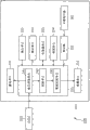
Fig. 6 is the diagrammatic sketch that details drawing illustrates the topology example of the criminal of preventing unit 201.
Interface or the modulator-demodular unit of communication unit 254 through being used for wired lan (LAN) or WLAN, come and the miscellaneous equipment executive communication via network (comprising the Internet).Communication unit 254 obtains computer program and they is installed in the memory cell 253 via network (comprising the Internet) under the control of control module 231.
Where necessary, the criminal of preventing unit 201 is connected to driver element 255, so that computer program is installed in the memory cell 253 by the removable media 261 from the disk on being loaded in driver element 255, CD and magneto-optic disk or semiconductor memory.
The voltage that voltage measurement unit 241 is measured between the positive and negative terminal of the DSSC 203 that is made up of a plurality of battery units that are connected in series (being 24 battery units in the situation shown in Fig. 5 A).Want measured voltage be DSSC 203 each battery unit output voltage with.
Put aside electricity accumulating unit 232 from the electric power that DSSC 203 provides.
If judging unit 242 judges that the object near window 202 is the people that should provide alarm, then it notifies result of determination to alarm control module 243.Alarm control module 243 is controlled alarm unit 233 in response to the information that receives, so that alarm unit 233 provides alarm through the image on sound, message, the monitor, light (LED) or vibration.
[criminal's of preventing processing]
Above-mentioned processing is carried out according to process flow diagram shown in Figure 7 in the criminal of preventing unit 201.
The criminal of preventing handles and can be repeated to carry out by regular or irregular interval.That is, can set arbitrarily constantly or carry out the criminal of preventing in any time that the regulation incident takes place and handle.Perhaps, can be continuously and repeatedly carry out prevent criminal processing.
The criminal of preventing handles at the beginning, and the voltage measurement unit 241 of control module 231 is the voltage between the positive and negative terminal of measurement DSSC 203 in step S201 just.At step S202, judging unit 242 judges according to the amount that voltage reduces whether the object near window 202 is should be to its object that gives the alarm (for example, people).
If in step S203 judging unit 242 judge detected will the criminal of preventing object, then it advances to step S204.At step S204, alarm control module 243 control alarm units 233 are carried out actuation of an alarm.Like this, the criminal's of preventing processing finishes.
If in step S203 judging unit 242 judge detected object be not will the criminal of preventing object, then its skips steps S204, and prevent criminal processing end.
As stated, the criminal of preventing unit 201 can be through the voltage between the terminal of measuring the DSSC 203 that is made up of the battery unit that is connected in series, according to the amount of voltage reduction come easily to discern will the criminal of preventing object.In other words, motion sensor window 200 details of inspected object easily.
Or rather, motion sensor window 200 has not only been simplified the structure (the perhaps circuit of DSSC 203) of window 202, but also has simplified anti-criminal's processing of anti-criminal unit 201.Therefore, motion sensor window 200 has not only reduced exploitation and production cost, but also has reduced power consumption.In addition, the structure of simplification has improved reliability.
The amount that above-mentioned judging unit 242 reduces according to voltage or the size of detected object judge detected object whether be will the criminal of preventing object.But, can be modified to judging unit 242 and measure the length of the time that is used to detect.In this situation, if greater than the object of the prescribed level arrival to be detected time longer than specified length, then judging unit 242 judge detected object be will the criminal of preventing object.
Such modification will reduce the possibility of error-detecting.
3. the 3rd embodiment
[card type telepilot]
Fig. 8 is the diagrammatic sketch that illustrates the example of having used card type telepilot of the present invention.
The user interface of card type telepilot 300 comprises six button area 302-1 to 302-6.If do not need to discern individually this six button area 302-1 to 302-6, then hereinafter will be referred to as button area 302 to them.The number of button area 302, size and shape are unfettered.The shape of each button area 302 can be different with another.
Button area 302 is as button.Each button area 302 has DSSC 311.DSSC 311 in each button area 302 receives the place generating of sunshine at it.When the user utilizes its finger touch (perhaps blocking) DSSC 311, by DSSC 311 generation outages of shading.
Each member of DSSC 311 is connected in series, and the combination of DSSC 311 has the terminal that is connected to control module 301, and is as shown in Figure 8.
In Fig. 8, the line that connects each member of DSSC 311 explains that schematically they are connected in series together, but they are not practical wiring.In fact, the combination of DSSC 311 is connected to control module 301 through its two terminals.Each member of DSSC 311 can connect by random order, as long as they are connected in series.
As shown in Figure 8, the DSSC 311 of each button area 302 has the battery unit of different numbers.In Fig. 8; Button area 302-1 has the DSSC 311 of 1 battery unit; Button area 302-2 has the DSSC 311 of 2 battery units, and button area 302-3 has the DSSC 311 of 3 battery units, and button area 302-4 has the DSSC 311 of 4 battery units; Button area 302-5 has the DSSC 311 of 5 battery units, and button area 302-6 has the DSSC 311 of 6 battery units.Control module 301 is known the battery unit number that is arranged in the DSSC 311 in each button area 302 in advance.Each button area 302 can have the DSSC 311 of necessary a plurality of battery units, as long as control module 301 is known the battery unit number in advance.
Because the number of the battery unit of the DSSC 311 in each button area is different, so the number of the battery unit of the DSSC 311 of generation outage is also different because of button area 302 when user's action button zone 302.In other words, if control module 301 is measured the voltage of combination and detected the amount that its voltage reduces, then it can identify the button area 302 of user's operation.
The DSSC 311 of each button area 302 can have the battery unit of given number, so that be different from (not operated) other button area 302 by one or more button area 302 of user's operation.For example, the battery unit of DSSC 311 can be arranged as followsly.Button area 302-1 has 1 battery unit; Button area 302-2 has 2 battery units, and button area 302-3 has 4 battery units, and button area 302-4 has 8 battery units; Button area 302-5 has 13 battery units, and button area 302-6 has 29 battery units.
Mention that along band the size of each DSSC 311 is difference (that is, the generating capacity of each DSSC 311 or voltage can be different each other) each other.
No matter adopt which kind of method, the amount that the battery unit of DSSC 311 all is arranged such that voltage that control module 301 can generate from all members by DSSC 311 in each button area 302, reduce according to voltage is discerned operated button area 302.
After identifying by the button area 302 of user's operation, control module 301 sends and the button area 302 corresponding control signals (with the form of radio signal) that identify to the electronic equipment by 300 controls of card type telepilot through antenna 303.Mention that along band the transmission of control signal and reception can meet any communication standard.They can be accomplished through using electromagnetic wireless communication or infrared communication.Communication standard can comprise bluetooth (Bluetooth, registered trademark) and Wi-Fi (registered trademark).
Above-mentioned card type telepilot 300 need be as the movable part such as button (this movable part is owing to outmoded deterioration is easy to be out of order) of user interface.Therefore, card type telepilot 300 has high reliability.
[control module]
Fig. 9 is the block diagram of example that illustrates the primary structure of control module 301.
As shown in Figure 9, control module 301 has signal processing unit 321, electricity accumulating unit 322 and memory cell 323.
Voltage between the positive and negative terminal of the combination of a plurality of DSSC 311 that voltage measurement unit 331 measurements are connected in series.The voltage that operating position recognition unit 332 bases provide from voltage measurement unit 331 is measured the amount (the perhaps reduction amount of generating) from the voltage reduction of the voltage of original state (button area 302 keeps not touched by the user), and operating position recognition unit 332 is discerned by the button area 302 of user's operation then.Operating position recognition unit 332 sends to output information selected cell 333 with the result.
Output information selected cell 333 is selected and the button area 302 corresponding output informations (control information) that touched by the user that gone out through the information Recognition that receives from operating position recognition unit 332.Between the user is to the operator scheme of button area 302 and output information (perhaps card type telepilot 300 sends to the control information of wanting controlled electronic equipment), have the corresponding relation of setting up in advance, this corresponding relation is stored in the memory cell 323.
Output information selected cell 333 utilizes this corresponding relation to select the corresponding output information of operator scheme with the button area 302 that has been identified by operating position recognition unit 332.Output information selected cell 333 sends to transmitting element 334 with selected output information.
Mention that along band output information selected cell 333 can add arbitrary parameter and out of Memory to the output information of such selection where necessary, and sends it to transmitting element 334.For example, signal processing unit 321 can be measured the time span in user's touch button zone 302, and output information selected cell 333 can add the information of relevant running time to selected output information to send it to transmitting element 334.Like this, card type telepilot 300 can change controlled quentity controlled variable according to running time length, to carry out control by variety of way.
Transmitting element 334 outwards sends from output information selected cell 333 through antenna 303, with the form of radio signal next output information is provided.
Suppose as user also not during action button zone 302 original state that card type telepilot 300 is taked shown in Figure 10 A.Shown in Figure 10 B and 10C, when the user utilizes its finger 351 to touch any button area 302, the DSSC 311 that finger 351 has blocked in the button area 302 that is touched, thus cause its generation outage.This voltage that has produced like the indicated output voltage of the curve map among Figure 11 reduces.
Suppose that the original state shown in Figure 10 A has provided the indicated I-V characteristic of curve 361.When user shown in Figure 10 B utilizes its finger 351 when having touched button area 302-2, two DSSC 311 are by shading, and output voltage reduced from the output voltage of original state, are shown like curve 362 indicated I-V characteristics.
In addition, when the user utilizes its finger 351 when having touched button area 302-4 shown in Figure 10 C, four DSSC 311 have been reduced by shading and the output voltage output voltage from original state, are shown like curve 363 indicated I-V characteristics.
As stated, the amount of voltage reduction depends on the number of the DSSC 311 that is arranged in the button area 302 that has been touched and changes.Therefore, operating position recognition unit 332 can easily be discerned by the position of the button area 302 of user's operation.In other words, card type telepilot 300 more details of inspected object easily.
[signal output is handled]
Aforementioned processing is accomplished by signal processing unit 321, and signal processing unit 321 comes work according to the process flow diagram that is used for signal output processing shown in Figure 12.
Can repeat this signal output by regular or irregular interval handles.For example, can set arbitrarily constantly or any time this processing of execution of regulation incident take place.Perhaps, can be continuously and repeatedly carry out and to handle.
When beginning was handled in signal output, the voltage measurement unit 331 of signal processing unit 321 was measured the voltage between the positive and negative terminal at DSSC 311 at step S301.Next, voltage measurement unit 331 judges at step S302 whether voltage has reduced.If judge that voltage reduces, then handle advancing to step S303.
At step S303, the amount that operating position recognition unit 332 reduces according to voltage is come identifying operation position (button area 302 that has perhaps been touched by the user).At step S304, output information selected cell 333 is selected the control information that will export according to the operating position of the button area that identifies.
At step S305, transmitting element 334 sends the output information (control information) through the processing selecting among the step S304 through antenna 303.
If do not exist voltage to reduce (perhaps original state is held) in step S302 judgement, the then processing among the voltage measurement unit 331 skips steps S303 to S305, and end signal output is handled.
As stated, through in button area 302, using DSSC as sensor, card type telepilot 300 is worked under the situation of external power source not having.In addition, the simple wiring that card type telepilot 300 allows between control module 301 and DSSC 311, and make control module 301 can carry out signal output processing more simply.As a result, card type telepilot 300 has not only reduced exploitation and production cost, but also has reduced power consumption.In addition, give the credit to its simple structure, card type telepilot 300 has also improved reliability.
The shape of above-mentioned card type telepilot is unfettered.
In order to set forth typical application of the present invention, anti-criminal unit (motion detection window) and telepilot (card type telepilot) have been described above.But the present invention can be applied to having any apparatus and the system of sensing function.
Some application comprise the user interface that is used for the electrical equipment such as personal computer, AV equipment and household electrical appliance; The user interface that is used for the portable terminal such as portable game machine, counter and portable phone; And the sensor that is used for light fixture, automatically-controlled door, room discrepancy surveillance and disaster prevention system.
Said system is designed so that change according to generated energy (perhaps voltage reduce amount) discerns the number of the battery unit of generating, thus the size of inspected object, shape or position.It can be modified to identification by the area of the part of object shading.
The example of such modification is described with reference to figure 13A and 13B.Sensor shown in Figure 13 A comprises DSSC 402 and control module 401, and they interconnect.Control module 401 is to be used in the same manner as described above the sensor that the change that the electric power according to DSSC 402 generates (perhaps voltage reduce amount) detects arbitrary objects, and difference is that DSSC 402 only has a battery unit.
So showing, Figure 13 A do not have object not detect the sensor of arbitrary objects as yet near DSSC 402.In this state, DSSC 402 has provided like the indicated I-V characteristic of the curve in the curve map of this figure bottom 411.
The DSSC 402 of the shown sensor of the diagrammatic sketch among Figure 13 B (identical with the sensor shown in Figure 13 A) has the shade 403 that appears at DSSC 402 object nearby.
In this state, the I-V characteristic is indicated by the curve 412 in the curve map of this figure bottom.In other words, shade 403 has reduced the surface area that is used to generate electricity of DSSC 402, and the I-V characteristic of DSSC402 (indicated) and surface area like curve 412 reduce change pro rata, thereby produced voltage reduction (making that perhaps generating reduces).
As stated, the electric power of DSSC 402 generation (perhaps voltage) is approximate changes with its surface area pro rata.In other words, control module 401 change that can generate according to electric power (perhaps voltage reduce amount) detect battery unit by the shading area.By this way, the more specifically size and the shape of inspected object of control module 401.(size that can detected object can be less than the size of single battery unit.)
Figure 14 A to 14C shows another example of application.Sensor shown in Figure 14 A links to each other with control module 421, and its change that generates according to the electric power of DSSC 422 (the perhaps amount of voltage reduction) detects the arbitrary objects of proximity transducer.DSSC 422 comprises a plurality of battery units 423 of being connected in series.In other words, control module 421 detects the voltage between the terminal of combination of the battery unit of being connected in series.
Suppose that an object is incident upon on one or more battery units 423, shown in Figure 14 A near DSSC 422 and its shade 431.In this case, the generated energy of each battery unit 423 (perhaps voltage) is similar to the reduction with shade with being in proportion, as top described with reference to figure 13A and 13B.
Promptly; When the object that do not exist near DSSC 422 (perhaps when DSSC 422 not by shading time); The I-V characteristic of DSSC 422 is indicated by the curve among Figure 14 B 441; But when an object was incident upon 423 last times of one or more battery unit (as DSSC 422 during by shading) near DSSC 422 and its shade 431, the I-V characteristic of DSSC 422 is indicated by the curve among Figure 14 C 442.
Like this, the I-V characteristic of DSSC 422 (perhaps electric power generates or the voltage reduction) basis changes near the size of the shade 431 of the object of DSSC 422.Therefore, control module 421 detects the change (perhaps voltage reduction) that electric power generates, thereby detects the size of the shade 431 that has covered battery unit 423 parts of not generating electricity.By this way, control module 421 can detect size and the shape near the object of DSSC422.
So control module 421 can be discerned the size or the shape (control module 421 can be discerned details) of the object littler than single battery unit.That is the more details of inspected object easily of the sensor shown in Figure 13 A and 13B and Figure 14 A to 14C.
Give the credit to that a plurality of battery units are used shown in Figure 14 A, control module 421 can easily detect each battery unit has by shading (perhaps, the size of the not power generation region of each battery unit) for how many parts.In other words, control module 421 is the size and the shape of inspected object more specifically, and position that can inspected object.
If using with silicon is the sensor that solar cell substitutes DSSC 422, then generated energy with changed pro rata by the area of the battery unit of cast shadow.But as stated, even a battery unit generation outage, its voltage also greatly reduces.Therefore, it is difficult to detect size, shape and the position of object.
Form contrast with it, even DSSC 422 also continues generating during by the object shading when the part of its battery unit, although institute's generated energy and being reduced pro rata by the area of shading battery unit.Therefore, more specifically size, present situation and the position of inspected object of control module 421.
Above-mentioned a series of processing can be accomplished through hardware and software.
Under the situation that above-mentioned a series of processing are accomplished through software, the program that constitutes software can be installed from network or recording medium.
Recording medium comprises disk (comprising floppy disk), CD (comprising CD-ROM (compact disk-ROM (read-only memory)) and DVD (digital versatile disc)) and magneto-optic disk (MD (mini-disk)), and they comprise record program and quilt above that and allot to the user with delivery program.It also comprises the removable media 261 of semiconductor memory.It also comprises the hard disk that is loaded on memory cell 253 or 323.
Aforementioned calculation machine program can be the program carried out by the illustrated time sequencing of this instructions or executed in parallel or the program carried out as required.
The step that is used for describing the program that is recorded in recording medium can be arranged to above-mentioned time sequencing or parallel order, perhaps can be disposed in each process.
The above structure of explaining as an equipment (perhaps processing unit) can comprise two or more equipment (perhaps processing unit).Perhaps, more than being illustrated as the structure with two or more equipment (or processing unit) can be the structure that only has an equipment (or processing unit).Except above-mentioned those equipment, said structure can also combine with miscellaneous equipment (or processing unit).As long as the formation of total system is identical in fact with structure, the part of a certain equipment (or processing unit) can be combined in the miscellaneous equipment (or processing unit).In other words, embodiments of the invention be not limited to above-mentioned those, but can make amendment by variety of way within the scope of the invention.
The present invention comprises the relevant theme of the disclosed theme of patented claim JP 2010-157540 formerly with the Japan of submitting to Jap.P. office on July 12nd, 2010, and the full content of this application is incorporated into this by reference.
Claims (8)
1. messaging device comprises:
Voltage measurement unit is configured to measure the voltage between the positive and negative terminal of combination of a plurality of DSSCs that are connected in series; With
Judging unit; The number of the DSSC that the amount that the voltage that is configured to descend according to the voltage between the positive and negative terminal of the voltage between said positive and negative terminal from original state that is recorded by said voltage measurement unit reduces is confirmed not generate electricity; In said original state, all DSSCs in the said combination all generate electricity.
2. messaging device according to claim 1 also comprises:
The processing execution unit is configured to carry out processing according to the number of the DSSC of being confirmed by said judging unit that does not generate electricity.
3. messaging device according to claim 2, wherein
The number of the definite DSSC that does not generate electricity of said judging unit, thus estimate the size that is present in said combination object nearby, and judge according to the size that estimates whether this object will be processed, and
Said processing execution unit judges under the situation that said object will be processed at said judging unit, carries out the alarm of the existence that is used to notify object and handles.
4. messaging device according to claim 2, wherein
The DSSC of said combination is arranged such that they are divided in a plurality of zones of regulation by different numbers, and they are distributed in these zones,
The number of the definite DSSC that does not generate electricity of said judging unit, thus the zone of being operated by the user in said a plurality of zone discerned, and
Said processing execution unit is selected and the regional corresponding control signal that is identified, and the control signal that will select like this sends to miscellaneous equipment.
5. messaging device according to claim 1, wherein
The DSSC of said combination is arranged to array.
6. messaging device according to claim 1 also comprises:
Electricity accumulating unit is configured to put aside from the generating of the DSSC of said combination and the electric power that obtains.
7. messaging device according to claim 1, wherein
Said judging unit is confirmed that part of size that DSSC does not generate electricity in the said zone according to the amount that the voltage between the said positive and negative terminal reduces.
8. information processing method that is used for messaging device, said messaging device has the combination of a plurality of DSSCs that are connected in series, wherein
Said messaging device has voltage measurement unit, and this voltage measurement unit is measured the voltage between the positive and negative terminal of said combination;
Said messaging device also has judging unit; The number of the DSSC that the amount that the voltage that this judging unit descends according to the voltage between the positive and negative terminal of the voltage between said positive and negative terminal from original state that is recorded by said voltage measurement unit reduces is confirmed not generate electricity; In said original state, all DSSCs in the said combination all generate electricity.
Applications Claiming Priority (2)
| Application Number | Priority Date | Filing Date | Title |
|---|---|---|---|
| JP2010157540A JP5500367B2 (en) | 2010-07-12 | 2010-07-12 | Information processing apparatus and method |
| JP2010-157540 | 2010-07-12 |
Publications (1)
| Publication Number | Publication Date |
|---|---|
| CN102419184A true CN102419184A (en) | 2012-04-18 |
Family
ID=45439186
Family Applications (1)
| Application Number | Title | Priority Date | Filing Date |
|---|---|---|---|
| CN2011101939850A Pending CN102419184A (en) | 2010-07-12 | 2011-07-05 | Information processing device and information processing method |
Country Status (3)
| Country | Link |
|---|---|
| US (1) | US8645089B2 (en) |
| JP (1) | JP5500367B2 (en) |
| CN (1) | CN102419184A (en) |
Families Citing this family (6)
| Publication number | Priority date | Publication date | Assignee | Title |
|---|---|---|---|---|
| JP5500367B2 (en) * | 2010-07-12 | 2014-05-21 | ソニー株式会社 | Information processing apparatus and method |
| JP5961518B2 (en) * | 2012-10-05 | 2016-08-02 | 株式会社Nttドコモ | Input device |
| TWI461896B (en) * | 2012-11-07 | 2014-11-21 | Chih Chung Lin | Touch panel with photovoltaic conversion function |
| US9105765B2 (en) | 2012-12-18 | 2015-08-11 | Enphase Energy, Inc. | Smart junction box for a photovoltaic system |
| CN103605029B (en) * | 2013-11-29 | 2015-11-18 | 天津理工大学 | A kind of measuring method of DSSC electron lifetime distribution |
| US9787934B2 (en) * | 2014-01-15 | 2017-10-10 | Apple Inc. | Wireless devices with touch sensors and solar cells |
Citations (6)
| Publication number | Priority date | Publication date | Assignee | Title |
|---|---|---|---|---|
| JPS61118923A (en) * | 1984-11-15 | 1986-06-06 | セイコーエプソン株式会社 | Input switch mechanism for electronic appliance |
| CN1846288A (en) * | 2003-09-05 | 2006-10-11 | 索尼德国有限责任公司 | Tandem dye-sensitised solar cell and method of its production |
| JP2007173123A (en) * | 2005-12-22 | 2007-07-05 | Matsushita Electric Works Ltd | Switching device |
| CN101105714A (en) * | 2006-07-11 | 2008-01-16 | 索尼株式会社 | Information processing apparatus, information processing method, and program |
| CN101739750A (en) * | 2008-11-19 | 2010-06-16 | 苏州日宝科技有限责任公司 | Device for distinguishing diameters of mixing coins and counting by using CCD |
| US20100147354A1 (en) * | 2008-12-12 | 2010-06-17 | Toru Takehara | System for controlling power from a photovoltaic array by selectively configurating connections between photovoltaic panels |
Family Cites Families (7)
| Publication number | Priority date | Publication date | Assignee | Title |
|---|---|---|---|---|
| JP2002092755A (en) * | 2000-07-10 | 2002-03-29 | Canon Inc | Photovoltaic power generation system and control method for photovoltaic power generation system |
| JP3826689B2 (en) * | 2000-07-31 | 2006-09-27 | 松下電工株式会社 | Brightness sensor and lighting device with brightness sensor |
| EP1528580B2 (en) * | 2003-01-15 | 2015-07-01 | Nippon Shokubai Co., Ltd. | Dye-sensitized type solar cell |
| JP2008304384A (en) * | 2007-06-08 | 2008-12-18 | Panasonic Electric Works Co Ltd | Infrared light detector |
| WO2009129030A2 (en) * | 2008-04-14 | 2009-10-22 | Applied Materials, Inc. | Solar parametric testing module and processes |
| JP2011249790A (en) * | 2010-04-28 | 2011-12-08 | Kyocera Corp | Solar battery device |
| JP5500367B2 (en) * | 2010-07-12 | 2014-05-21 | ソニー株式会社 | Information processing apparatus and method |
-
2010
- 2010-07-12 JP JP2010157540A patent/JP5500367B2/en not_active Expired - Fee Related
-
2011
- 2011-07-05 US US13/176,257 patent/US8645089B2/en not_active Expired - Fee Related
- 2011-07-05 CN CN2011101939850A patent/CN102419184A/en active Pending
Patent Citations (6)
| Publication number | Priority date | Publication date | Assignee | Title |
|---|---|---|---|---|
| JPS61118923A (en) * | 1984-11-15 | 1986-06-06 | セイコーエプソン株式会社 | Input switch mechanism for electronic appliance |
| CN1846288A (en) * | 2003-09-05 | 2006-10-11 | 索尼德国有限责任公司 | Tandem dye-sensitised solar cell and method of its production |
| JP2007173123A (en) * | 2005-12-22 | 2007-07-05 | Matsushita Electric Works Ltd | Switching device |
| CN101105714A (en) * | 2006-07-11 | 2008-01-16 | 索尼株式会社 | Information processing apparatus, information processing method, and program |
| CN101739750A (en) * | 2008-11-19 | 2010-06-16 | 苏州日宝科技有限责任公司 | Device for distinguishing diameters of mixing coins and counting by using CCD |
| US20100147354A1 (en) * | 2008-12-12 | 2010-06-17 | Toru Takehara | System for controlling power from a photovoltaic array by selectively configurating connections between photovoltaic panels |
Also Published As
| Publication number | Publication date |
|---|---|
| JP2012023072A (en) | 2012-02-02 |
| JP5500367B2 (en) | 2014-05-21 |
| US20120010834A1 (en) | 2012-01-12 |
| US8645089B2 (en) | 2014-02-04 |
Similar Documents
| Publication | Publication Date | Title |
|---|---|---|
| CN102419184A (en) | Information processing device and information processing method | |
| CN103217573B (en) | Electricity monitoring arrangement, electricity surveillance and electricity supervision method | |
| US9196142B2 (en) | Method and system for managing consumption of heterogeneous resources | |
| CN102227740A (en) | Electric power control support device and electric power control support method | |
| CN104052857A (en) | Control device and method for mobile device | |
| CN106714104A (en) | Method and apparatus for identifying base station point of user activity area | |
| CN108181827A (en) | Backlog reminding method, device, terminal and medium | |
| CN109947496A (en) | Application program preloads method, apparatus, storage medium and mobile terminal | |
| CN107438998A (en) | Close detection means and method, close to inductive pick-up, terminal device | |
| US11119603B2 (en) | Touch control chip, electronic device having the same and touch detection method therefor | |
| CN105335653A (en) | Abnormal data detection method and apparatus | |
| CN103492884A (en) | Low average velocity pedestrial motion identification | |
| JP4595611B2 (en) | Monitoring system | |
| US20220085758A1 (en) | Detection condition determining method, apparatus, and photovoltaic system | |
| CN106297628B (en) | Display screen brightness adjusting method and device | |
| CN106462310A (en) | Touch chip and method of using same to detect touch points of touch screen | |
| CN105910620B (en) | The processing method and processing device of step counting data | |
| US11283401B2 (en) | System and method for determining a state of a photovoltaic panel | |
| KR101176012B1 (en) | Monitoring system of solar panel and method thereof | |
| JP2012023072A5 (en) | ||
| KR102405787B1 (en) | Hazardous gas alerting method and system | |
| WO2023216558A1 (en) | Self-inspection method for photovoltaic assembly, and electronic device and energy storage device | |
| CN108009068B (en) | Information recording method, information recording device and intelligent terminal | |
| CN116388690A (en) | Method for detecting operation state of photovoltaic panel, electronic equipment and storage medium | |
| CN103746753A (en) | Data prediction method based on cognitive wireless network |
Legal Events
| Date | Code | Title | Description |
|---|---|---|---|
| C06 | Publication | ||
| PB01 | Publication | ||
| C10 | Entry into substantive examination | ||
| SE01 | Entry into force of request for substantive examination | ||
| C02 | Deemed withdrawal of patent application after publication (patent law 2001) | ||
| WD01 | Invention patent application deemed withdrawn after publication |
Application publication date: 20120418 |