CN102407855A - Explosion-proof storage battery electric locomotive - Google Patents
Explosion-proof storage battery electric locomotive Download PDFInfo
- Publication number
- CN102407855A CN102407855A CN2011104180832A CN201110418083A CN102407855A CN 102407855 A CN102407855 A CN 102407855A CN 2011104180832 A CN2011104180832 A CN 2011104180832A CN 201110418083 A CN201110418083 A CN 201110418083A CN 102407855 A CN102407855 A CN 102407855A
- Authority
- CN
- China
- Prior art keywords
- igbt module
- motor
- explosion
- speed governing
- variable frequency
- Prior art date
- Legal status (The legal status is an assumption and is not a legal conclusion. Google has not performed a legal analysis and makes no representation as to the accuracy of the status listed.)
- Pending
Links
Images


Classifications
-
- Y—GENERAL TAGGING OF NEW TECHNOLOGICAL DEVELOPMENTS; GENERAL TAGGING OF CROSS-SECTIONAL TECHNOLOGIES SPANNING OVER SEVERAL SECTIONS OF THE IPC; TECHNICAL SUBJECTS COVERED BY FORMER USPC CROSS-REFERENCE ART COLLECTIONS [XRACs] AND DIGESTS
- Y02—TECHNOLOGIES OR APPLICATIONS FOR MITIGATION OR ADAPTATION AGAINST CLIMATE CHANGE
- Y02T—CLIMATE CHANGE MITIGATION TECHNOLOGIES RELATED TO TRANSPORTATION
- Y02T30/00—Transportation of goods or passengers via railways, e.g. energy recovery or reducing air resistance
Landscapes
- Electric Propulsion And Braking For Vehicles (AREA)
Abstract
The invention relates to an explosion-proof storage battery electric locomotive which is provided with a driving part with simple structure, long service life, high transmission efficiency, low failure rate and small operation noise and a braking part with rapid reaction, high safe factor and energy conservation. The locomotive comprises a carframe, wherein the carframe is provided with an electric part, an explosion-proof storage battery power supply device, the driving part and a mechanically braking part; the driving part comprises a motor; shaft heads at two ends of the driving part are connected with the carframe through a guiding frame and a damping spring; the motor of the driving part comprises a shaft; the shaft is externally and fixedly connected with an inner stator support; the inner stator support is externally and fixedly connected with an inner stator; a shell is arranged outside the shaft in a mode of rotating relative to the shaft; a permanent magnet is fixedly arranged in the shell; the inner stator is corresponding to the permanent magnet and is positioned in the permanent magnet; a power supply cable of the motor is led out from one end of the shaft, the other end of the power supply cable of the motor is connected with speed-regulating IGBT (insulated gate bipolar transistor) modules; and the power supply cable of the motor is connected with the middle three ends of a three-phase bridge circuit composed of the speed regulating IGBT modules.
Description
Technical field
The present invention relates to a kind of electric locomotive, relate in particular to a kind of flame proof battery locomotive.
Background technology
At present; Traditional flame proof battery locomotive comprises parts such as vehicle frame part, drive part, brake portion, electric part, explosion-proof battery supply unit; Mostly type of drive is that the flame-proof type DC traction motor passes to wheel through secondary or primary gear speed reducing device changeing distance; The flame-proof type DC traction motor is worked with the series excitation form; Through the DC chopped-wave controller explosion-proof battery power line voltage is reduced the speed that changes series excitation DC motor, thereby realize controls such as starting, operation electric locomotive.This type of drive exists a lot of not enough, and is big like complicated in mechanical structure, volume, is not easy to the dismounting maintenance, machinery driving efficiency is low, service life is short, it is big to move noise; Electric motor structure is complicated, has friction between carbon brush and the commutator, and efficient is low, service life is short, fault rate is high.
Tradition explosion-proof battery formula electric locomotive brake portion adopts the brake mode of mono-mechanical friction more; Promptly through handwheel rotational lead screw drivening rod mechanism, through increasing slipper (cast iron matter) and wheel (steel) thus between contact pressure produce friction and stop locomotive operation.High temperature is reacted slowly, after braking, is prone to produce to this brake mode; Be not suitable for using all over the colliery in step at high gas and coal dust; Also be prone to when emergency braking, make wheel lockup, cause accidents such as derailing, this brake mode exists that safety factor is low, deficiency such as waste energy.
Summary of the invention
The purpose of this invention is to provide a kind of flame proof battery locomotive, this flame proof battery locomotive drive part is simple in structure, and long service life, driving efficiency are high, fault rate is low, the operation noise is little, and the brake portion reaction is fast, safety factor is high, energy savings.
For realizing above-mentioned purpose, the technical scheme that the present invention adopts is:
A kind of flame proof battery locomotive; Comprise vehicle frame, electric part, explosion-proof battery supply unit, drive part and mechanical braking part are installed on the vehicle frame, drive part includes electrical motor; The two ends spindle nose of drive part links to each other with vehicle frame with damping spring through drawing strickle guide; The electrical motor of drive part includes axle, it is characterized in that: the axle external fixation is connected with internal stator and supports, and internal stator supports external fixation and is connected with internal stator; The outer shell that is rotatably installed with relatively of axle; The shell internal fixation is equipped with permanent magnet, and internal stator is corresponding with permanent magnet, and internal stator is positioned at permanent magnet; Axle one end leads to the electrical motor supply cable; The electrical motor supply cable other end is connected with speed governing IGBT module, and the electrical motor supply cable links to each other with middle three ends of three-phase bridge circuit that speed governing IGBT module is formed, and the positive pole of explosion-proof battery supply unit is connected with the three-phase bridge circuit positive terminal that speed governing IGBT module is formed through the electric braking IGBT module of reverse incircuit; The negative pole of explosion-proof battery supply unit directly is connected with the three-phase bridge circuit negative pole end that speed governing IGBT module is formed; Three-phase bridge circuit positive terminal and negative pole end that speed governing IGBT module is formed are parallel with filter capacitor, are set with motor current sensor on the three end connecting wires in the middle of the three-phase bridge circuit that electrical motor supply cable and speed governing IGBT module are formed, and are set with the electric braking current sensor on the positive pole of explosion-proof battery supply unit and the electric braking IGBT module connecting wire; Be connected with the variable frequency control part on electric braking current sensor and the motor current sensor together altogether; Lead-out terminal on electric braking current sensor and the motor current sensor and terminals for power supplies link to each other with the corresponding terminal of variable frequency control part respectively, and speed governing IGBT module is connected with variable frequency control corresponding terminal partly respectively with the trigger terminal of electric braking IGBT module, and the filter capacitor two ends are connected with variable frequency control corresponding terminal partly; Variable frequency control partly is connected with control desk, and the terminal of control desk is connected through signal wire (SW) with the corresponding terminal of variable frequency control part.
The type of drive that the present invention adopts is that many magnetic poles of flame-proof type minor decided at the higher level but not officially announced permanent-magnet synchronous traction motor directly passes to wheel through motor housing changeing distance; Rely on the permanent change that realizes electromotor velocity apart from the variable frequency regulating speed control device of changeing, thus controls such as the starting of realization electric locomotive, operation.Brake portion adopts traditional mechanical friction and regeneration electric braking dual mode.Regeneration electric braking principle is: locomotive goes with certain speed, needs glancing impact, stops the synchronous motor power supply to drive wheels; Electrical motor is operated in generating state; Give electric locomotive explosion-proof battery supply unit constant-current charge after three plase alternating current process electric system rectification of sending and the controlled copped wave, electric current produces the commentaries on classics distance in contrast to the electrical motor rotation direction, thereby realizes electric braking; The power storage that to brake simultaneously generation again supplies locomotive to use in storage battery.The present invention adopts the traditional mechanical brake mode when low cruise and Parking; In cruising, adopt the regeneration electrical braking modes; Fundamentally solved the problem that existing accumulator loco motive type of drive and brake mode exist, type of drive is simple in structure, compact, be convenient to the dismounting maintenance, machinery driving efficiency is high, it is little to move noise, and electrical motor adopts strong magnetic permanent magnet to make excitation; Improve motor efficiency 15%; Saves energy is about 12%, and the operation part has only antifriction-bearing box to have mechanical contact, so durability is high, long service life.Two kinds of brake mode can be had complementary advantages, and improve electric locomotive deceleration and stopping performance and safety performance, also play energy savings simultaneously, reduce the effect that consumes.
Description of drawings
Fig. 1 is a structural representation of the present invention;
Fig. 2 is the birds-eye view of Fig. 1;
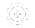
Fig. 3 is the structural representation of drive part among Fig. 1;
Fig. 4 is the A-A cutaway view of Fig. 3;
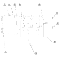
Fig. 5 is an electrical schematic diagram of the present invention.
In the accompanying drawing:
1, vehicle frame; 2, electric part; 3, explosion-proof battery supply unit; 4, drawing strickle guide; 5, drive part; 6, mechanical braking part; 7, damping spring; 8, electrical motor supply cable; 9, internal stator supports; 10, internal stator; 11, permanent magnet; 12, shell; 13, wheel nave; 14, electric motor end cap; 15, esplosion isolating cover; 16, bearing; 17, bearing cap shim; 18, axle; 19, control desk; 20, variable frequency control part; 21, speed governing IGBT module; 22, preceding electrical motor; 23, back electrical motor; 24, electric braking IGBT module; 25, filter capacitor; 26, motor current sensor; 27, electric braking current sensor.
The specific embodiment
Below in conjunction with accompanying drawing and specific embodiment the present invention is further described:
A kind of flame proof battery locomotive; Extremely shown in Figure 5 like Fig. 1; Comprise vehicle frame 1, electric part 2, explosion-proof battery supply unit 3, drive part 5 and mechanical braking part 6 are installed on the vehicle frame 1, drive part 5 includes electrical motor; The two ends spindle nose of drive part 5 links to each other with vehicle frame 1 with damping spring 7 through drawing strickle guide 4; The electrical motor of drive part 5 includes axle 18, and axle 18 external fixation are connected with internal stator and support 9, and internal stator supports 9 external fixation and is connected with internal stator 10; The axle 18 outer shells 12 that are rotatably installed with relatively; Shell 12 internal fixation are equipped with permanent magnet 11, and internal stator 10 is corresponding with permanent magnet 11, and internal stator 10 is positioned at permanent magnet 11; Axle 18 1 ends lead to electrical motor supply cable 8; Electrical motor supply cable 8 other ends are connected with speed governing IGBT module 21, and electrical motor supply cable 8 links to each other with middle three ends of three-phase bridge circuit that speed governing IGBT module 21 is formed, and the positive pole of explosion-proof battery supply unit 3 is connected with the three-phase bridge circuit positive terminal that speed governing IGBT module 21 is formed through the electric braking IGBT module 24 of reverse incircuit; The negative pole of explosion-proof battery supply unit 3 directly is connected with the three-phase bridge circuit negative pole end that speed governing IGBT module 21 is formed; Three-phase bridge circuit positive terminal and negative pole end that speed governing IGBT module 21 is formed are parallel with filter capacitor 25, are set with motor current sensor 26 on the three end connecting wires in the middle of the three-phase bridge circuit that electrical motor supply cable 8 and speed governing IGBT module 21 are formed, and are set with electric braking current sensor 27 on the positive pole of explosion-proof battery supply unit 3 and electric braking IGBT module 24 connecting wires; Be connected with variable frequency control part 20 on electric braking current sensor 27 and the motor current sensor 26 together altogether; Electric braking current sensor 27 links to each other with the corresponding terminal of variable frequency control part 20 respectively with lead-out terminal and terminals for power supplies on the motor current sensor 26, and speed governing IGBT module 21 is connected with the corresponding terminal of variable frequency control part 20 respectively with the trigger terminal of electric braking IGBT module 24, and filter capacitor 25 two ends are connected with the corresponding terminal of variable frequency control part 20; Variable frequency control part 20 is connected with control desk 19, and the terminal of control desk 19 is connected through signal wire (SW) with variable frequency control part 20 corresponding terminals.
The present invention is a kind of explosion-proof battery frequency control motor car, has overcome the deficiency that existing explosion-proof battery formula electric locomotive exists on type of drive and brake mode.
Like Fig. 1, shown in Figure 2; The two ends spindle nose of drive part 5 links to each other with vehicle frame 1 with damping spring 7 through the drawing strickle guide 4 that can only move up and down; Axle 18 can only move up and down with respect to vehicle frame 1, can not rotate, and can realize not having speed reduction gearing after drive part 5 energisings and drive locomotive operation.
Like Fig. 3, shown in Figure 4; Internal stator 10 is all fixed through key with axle 18 with internal stator support 9, internal stator support 9; Permanent magnet 11 bonds together with shell 12; Shell 12, wheel nave 13, electric motor end cap 14 and bearing cap shim 17 link to each other through bolt, many magnetic poles of above component set-up minor decided at the higher level but not officially announced permanent-magnet synchronous traction motor, and electrical motor supply cable 8 is drawn from axle 18 1 ends.This electrical motor is a flame-proof type, realizes the flame proof requirement through esplosion isolating cover 15 and electric motor end cap 14.
In Fig. 5, be the electric diagram of electric part 2 in the big frame of broken lines, velocity setting device, motor commutation switch are arranged in the control desk 19, speed and direction signal that control desk 19 produces are delivered to variable frequency control part 20 through cable.Power unit, IGBT drive part, system controlled by computer part are arranged in the variable frequency control part 20.Power unit provides power supply for variable frequency control part 20; When locomotive need move; The system controlled by computer part is handled the permanent commentaries on classics of back output apart from three phase variable frequency rate control signal with the speed of control desk 19 generations and the current signal of direction signal and motor current sensor 26 generations; Control signal amplifies back control speed governing IGBT module 21 through the IGBT drive part, and then the three phase variable frequency electricity is provided for many magnetic poles of minor permanent-magnet synchronous traction motor decided at the higher level but not officially announced, and electrical motor is rotated with specific direction and speed.Electric locomotive moves when needing electric braking at a relatively high speed; The driver returns control handle to zero; System controlled by computer is partly handled back output constant-current charge control signal with the signal of control desk 19 generations and the braking current signal of electric braking current sensor 27 generations, control electric braking IGBT module 24 after the amplification of control signal process IGBT drive part, and electrical motor is operated in generating state; The three plase alternating current that sends is through giving explosion-proof battery supply unit 3 constant-current charges after diode rectification and the 24 controlled copped waves of electric braking IGBT module in the speed governing IGBT module 21; Electric current produces the commentaries on classics distance in contrast to the electrical motor rotation direction, thereby realizes electric braking, and electric locomotive speed descends rapidly; Electric power generation voltage also descends, and variable frequency control part 20 stops electric braking control after dropping to setting value according to electric power generation voltage.
Claims (1)
1. flame proof battery locomotive; Comprise vehicle frame (1); Electric part (2), explosion-proof battery supply unit (3), drive part (5) and mechanical braking part (6) are installed on the vehicle frame (1); Drive part (5) includes electrical motor; The two ends spindle nose of drive part (5) links to each other with vehicle frame (1) with damping spring (7) through drawing strickle guide (4); The electrical motor of drive part (5) includes axle (18); It is characterized in that: axle (18) external fixation is connected with internal stator and supports (9); Internal stator supports (9) external fixation and is connected with internal stator (10); The outer shell (12) that is rotatably installed with relatively of axle (18); Shell (12) internal fixation is equipped with permanent magnet (11), and internal stator (10) is corresponding with permanent magnet (11), and internal stator (10) is positioned at permanent magnet (11); Axle (18) one ends lead to electrical motor supply cable (8); Electrical motor supply cable (8) other end is connected with speed governing IGBT module (21), and electrical motor supply cable (8) links to each other with middle three ends of three-phase bridge circuit that speed governing IGBT module (21) is formed, and the positive pole of explosion-proof battery supply unit (3) is connected with the three-phase bridge circuit positive terminal that speed governing IGBT module (21) is formed through the electric braking IGBT module (24) of reverse incircuit; The negative pole of explosion-proof battery supply unit (3) directly is connected with the three-phase bridge circuit negative pole end that speed governing IGBT module (21) is formed; Three-phase bridge circuit positive terminal and negative pole end that speed governing IGBT module (21) is formed are parallel with filter capacitor (25), are set with motor current sensor (26) on the three end connecting wires in the middle of the three-phase bridge circuit that electrical motor supply cable (8) and speed governing IGBT module (21) are formed, and are set with electric braking current sensor (27) on the positive pole of explosion-proof battery supply unit (3) and electric braking IGBT module (24) connecting wire; Electric braking current sensor (27) is gone up with being connected with variable frequency control part (20) altogether with motor current sensor (26); Lead-out terminal on electric braking current sensor (27) and the motor current sensor (26) and terminals for power supplies link to each other with the corresponding terminal of variable frequency control part (20) respectively, the trigger terminal of speed governing IGBT module (21) and electric braking IGBT module (24) respectively with variable frequency control partly the corresponding terminal of (20) be connected, filter capacitor (25) two ends and the variable frequency control partly corresponding terminal of (20) are connected; Variable frequency control part (20) is connected with control desk (19), and the terminal of control desk (19) is connected through signal wire (SW) with variable frequency control part (20) corresponding terminal.
Priority Applications (1)
| Application Number | Priority Date | Filing Date | Title |
|---|---|---|---|
| CN2011104180832A CN102407855A (en) | 2011-12-15 | 2011-12-15 | Explosion-proof storage battery electric locomotive |
Applications Claiming Priority (1)
| Application Number | Priority Date | Filing Date | Title |
|---|---|---|---|
| CN2011104180832A CN102407855A (en) | 2011-12-15 | 2011-12-15 | Explosion-proof storage battery electric locomotive |
Publications (1)
| Publication Number | Publication Date |
|---|---|
| CN102407855A true CN102407855A (en) | 2012-04-11 |
Family
ID=45910288
Family Applications (1)
| Application Number | Title | Priority Date | Filing Date |
|---|---|---|---|
| CN2011104180832A Pending CN102407855A (en) | 2011-12-15 | 2011-12-15 | Explosion-proof storage battery electric locomotive |
Country Status (1)
| Country | Link |
|---|---|
| CN (1) | CN102407855A (en) |
Cited By (6)
| Publication number | Priority date | Publication date | Assignee | Title |
|---|---|---|---|---|
| CN103532329A (en) * | 2013-10-31 | 2014-01-22 | 中煤科工集团重庆研究院有限公司 | Mine low-speed brushless generator |
| CN103723152A (en) * | 2013-12-30 | 2014-04-16 | 淮北阳光工矿机车制造有限责任公司 | Primary transmission walking device for mining explosion-proof type permanent magnetic electric locomotive |
| CN103723151A (en) * | 2013-12-30 | 2014-04-16 | 淮北阳光工矿机车制造有限责任公司 | Mining explosion-proof type primary transmission electric locomotive with permanent magnetic synchronous motor |
| CN108110940A (en) * | 2017-12-01 | 2018-06-01 | 太原理工大学 | A kind of separable frequency conversion explosion proof all-in-one machine shell device |
| CN111559391A (en) * | 2020-01-14 | 2020-08-21 | 中车资阳机车有限公司 | Two-shaft framework type storage battery locomotive for track |
| CN114448294A (en) * | 2021-11-10 | 2022-05-06 | 淮北矿业股份有限公司 | Control regulating circuit for storage battery electric locomotive |
Citations (6)
| Publication number | Priority date | Publication date | Assignee | Title |
|---|---|---|---|---|
| US20080179999A1 (en) * | 2007-01-25 | 2008-07-31 | Kabushiki Kaisha Toshiba | Motor drive system for railway vehicle |
| CN101380902A (en) * | 2007-09-04 | 2009-03-11 | 阿尔斯通运输公司 | Device for secure dynamic braking with a bipolar resistive element with permanent magnet motor |
| CN201604642U (en) * | 2010-03-02 | 2010-10-13 | 刘怀东 | Variable-frequency explosion-proof special storage battery electric locomotive for coal mines |
| CN201639491U (en) * | 2010-01-06 | 2010-11-17 | 青岛天信电气有限公司 | Explosion-proof intrinsically safe frequency converter used for mines |
| CN201971010U (en) * | 2011-03-04 | 2011-09-14 | 山西华鑫电气有限公司 | Explosion-proof storage battery gearless permanent-magnet synchronous traction electric locomotive |
| CN202400088U (en) * | 2011-12-15 | 2012-08-29 | 枣庄联鑫实业有限责任公司 | Electric locomotive with anti-exploding storage battery |
-
2011
- 2011-12-15 CN CN2011104180832A patent/CN102407855A/en active Pending
Patent Citations (6)
| Publication number | Priority date | Publication date | Assignee | Title |
|---|---|---|---|---|
| US20080179999A1 (en) * | 2007-01-25 | 2008-07-31 | Kabushiki Kaisha Toshiba | Motor drive system for railway vehicle |
| CN101380902A (en) * | 2007-09-04 | 2009-03-11 | 阿尔斯通运输公司 | Device for secure dynamic braking with a bipolar resistive element with permanent magnet motor |
| CN201639491U (en) * | 2010-01-06 | 2010-11-17 | 青岛天信电气有限公司 | Explosion-proof intrinsically safe frequency converter used for mines |
| CN201604642U (en) * | 2010-03-02 | 2010-10-13 | 刘怀东 | Variable-frequency explosion-proof special storage battery electric locomotive for coal mines |
| CN201971010U (en) * | 2011-03-04 | 2011-09-14 | 山西华鑫电气有限公司 | Explosion-proof storage battery gearless permanent-magnet synchronous traction electric locomotive |
| CN202400088U (en) * | 2011-12-15 | 2012-08-29 | 枣庄联鑫实业有限责任公司 | Electric locomotive with anti-exploding storage battery |
Non-Patent Citations (1)
| Title |
|---|
| 胡晓东等: "煤矿电机车变频调速系统设计与实现", 《煤矿机械》 * |
Cited By (10)
| Publication number | Priority date | Publication date | Assignee | Title |
|---|---|---|---|---|
| CN103532329A (en) * | 2013-10-31 | 2014-01-22 | 中煤科工集团重庆研究院有限公司 | Mine low-speed brushless generator |
| CN103532329B (en) * | 2013-10-31 | 2016-09-14 | 中煤科工集团重庆研究院有限公司 | Mine low-speed brushless generator |
| CN103723152A (en) * | 2013-12-30 | 2014-04-16 | 淮北阳光工矿机车制造有限责任公司 | Primary transmission walking device for mining explosion-proof type permanent magnetic electric locomotive |
| CN103723151A (en) * | 2013-12-30 | 2014-04-16 | 淮北阳光工矿机车制造有限责任公司 | Mining explosion-proof type primary transmission electric locomotive with permanent magnetic synchronous motor |
| CN103723151B (en) * | 2013-12-30 | 2016-05-11 | 淮北阳光工矿机车制造有限责任公司 | Mine anti-explosion permanent magnet type synchronous motor one-level driving motor car |
| CN108110940A (en) * | 2017-12-01 | 2018-06-01 | 太原理工大学 | A kind of separable frequency conversion explosion proof all-in-one machine shell device |
| CN108110940B (en) * | 2017-12-01 | 2019-11-12 | 太原理工大学 | A kind of separable frequency conversion explosion proof all-in-one machine shell device |
| CN111559391A (en) * | 2020-01-14 | 2020-08-21 | 中车资阳机车有限公司 | Two-shaft framework type storage battery locomotive for track |
| CN111559391B (en) * | 2020-01-14 | 2024-04-12 | 中车资阳机车有限公司 | Two-shaft frame type storage battery locomotive for track |
| CN114448294A (en) * | 2021-11-10 | 2022-05-06 | 淮北矿业股份有限公司 | Control regulating circuit for storage battery electric locomotive |
Similar Documents
| Publication | Publication Date | Title |
|---|---|---|
| CN105024509B (en) | The birotor wheel hub motor and its method of power transmission of four-wheel driving electric vehicle | |
| CN102407855A (en) | Explosion-proof storage battery electric locomotive | |
| CN101282071A (en) | Permanent magnetism synchronous wheel hub motor for directly driving electric vehicle wheel | |
| CN101633309A (en) | Series hybrid electric vehicle (SHEV) driving device and control method | |
| JP2013095414A (en) | Hybrid car system | |
| CN102386734A (en) | Permanent magnet synchronous motor for extended range electric automobile | |
| CN102005877A (en) | Energy-saving hub motor | |
| CN103522908A (en) | Self-energy electric vehicle | |
| CN101902088A (en) | Double-winding permanent magnet motor | |
| CN102416996B (en) | Electric bicycle with electric generator | |
| CN201971010U (en) | Explosion-proof storage battery gearless permanent-magnet synchronous traction electric locomotive | |
| CN201204530Y (en) | Permanent magnet synchronous hub motor for directly driving electric vehicle wheel | |
| CN103318046B (en) | A kind of pure electric light bus dynamic assembly | |
| CN101976920B (en) | Double rotor engine for pure electric car and control method thereof | |
| CN202400088U (en) | Electric locomotive with anti-exploding storage battery | |
| CN104638800B (en) | Bogie frame of the railway freight-car with shaft end generator and with the shaft end generator | |
| CN201970848U (en) | Wheel hub driving device and wheel hub driving electric vehicle adopting wheel hub driving device | |
| CN201553026U (en) | Hybrid power wheel side driving device | |
| CN204641379U (en) | Wheel hub electric motor of electric vehicle Two-wheeled system | |
| CN103280940A (en) | Moving motor and electric vehicle | |
| CN204605540U (en) | A kind of energy-saving reduction apparatus of battery-driven car | |
| CN201472138U (en) | HEV actuator | |
| CN102673379A (en) | Multifunctional hub driving device | |
| CN201400081Y (en) | Oil-electricity mixed power vehicle | |
| CN102101431A (en) | Hybrid power driving system and hybrid power vehicle |
Legal Events
| Date | Code | Title | Description |
|---|---|---|---|
| C06 | Publication | ||
| PB01 | Publication | ||
| C10 | Entry into substantive examination | ||
| SE01 | Entry into force of request for substantive examination | ||
| C02 | Deemed withdrawal of patent application after publication (patent law 2001) | ||
| WD01 | Invention patent application deemed withdrawn after publication |
Application publication date: 20120411 |