CN100575964C - Be used to measure the instrument of electric power - Google Patents
Be used to measure the instrument of electric power Download PDFInfo
- Publication number
- CN100575964C CN100575964C CN200410095483A CN200410095483A CN100575964C CN 100575964 C CN100575964 C CN 100575964C CN 200410095483 A CN200410095483 A CN 200410095483A CN 200410095483 A CN200410095483 A CN 200410095483A CN 100575964 C CN100575964 C CN 100575964C
- Authority
- CN
- China
- Prior art keywords
- voltage
- current
- instrument
- sample
- sampling
- Prior art date
- Legal status (The legal status is an assumption and is not a legal conclusion. Google has not performed a legal analysis and makes no representation as to the accuracy of the status listed.)
- Expired - Fee Related
Links
Images

Classifications
-
- G—PHYSICS
- G01—MEASURING; TESTING
- G01R—MEASURING ELECTRIC VARIABLES; MEASURING MAGNETIC VARIABLES
- G01R22/00—Arrangements for measuring time integral of electric power or current, e.g. electricity meters
- G01R22/06—Arrangements for measuring time integral of electric power or current, e.g. electricity meters by electronic methods
-
- G—PHYSICS
- G01—MEASURING; TESTING
- G01R—MEASURING ELECTRIC VARIABLES; MEASURING MAGNETIC VARIABLES
- G01R21/00—Arrangements for measuring electric power or power factor
- G01R21/133—Arrangements for measuring electric power or power factor by using digital technique
Abstract
The present invention relates to the electric power meter field, it utilizes digital signal processing so that obtain the consumption of electric energy by the integration of described electric power.Described instrument (1) comprises the voltage sensor (4) that produces analog voltage signal; Produce the current sensor (3) of analog current signal; Analog to digital converter (8) was included in for first sampling time to produce first sampling apparatus of first voltage sample and second sampling apparatus that produces first current sample in second sampling time; Phase compensation device (9) was adjusted for second sampling time with the phase shift between compensating analog voltage and current signal by comparing for first sampling time, thereby first voltage sample and first current sample of basic homophase is provided.Described instrument (1) is characterised in that and also comprises memory storage (11), be used for storing simultaneously first voltage sample and immediately following second voltage sample of sampling first voltage sample, or store first current sample simultaneously and immediately following second current sample of sampling first current sample.
Description
Technical field
The present invention relates to the electric power meter field, it utilizes digital signal processing so that obtain the consumption of electric energy by the integration of described electric power.
Background technology
The electric energy that can measuring equipment consumes with ammeter (electric utility meter) is provided as everyone knows.Electric current and the proportional analog signal conversion of voltage become to be used for the digital signal of digital signal processing in this instrument handle and the power lead that is measured.This switch process is realized by analog to digital converter.The product that digital signal easily can be multiplied each other and multiplies each other provides electric power then.Electric power is provided for the totalizer on the power lead that is measured then, and this totalizer produces and the proportional pulse of electric power.
This known problem that runs into ammeter is, the accuracy requirement of this instrument before each of voltage and current signal offers analog to digital converter, the voltage and current signal has correct phase relation.Be that phase relation should accurately be represented the phase relation in the power lead.Yet the filtering of voltage and current, amplification and isolation are to differ therebetween or instrument transformer and other circuit components of error are finished by comprising to bring.
For the foozle of the accuracy that obtains to require and compensation apparatus transformer and circuit component in time with the change of environmental exposure, the known solution of this problem provides the phase compensation device that is used for ammeter.A solution discloses in document US 5017860 like this, it discloses a kind of instrument, comprise compensation system, other signals sampling time and provides the more accurate indication of the power that uses on the power lead with the phase shift of bucking-out system relatively to be used for adjusting a signal (curtage).
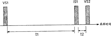
Yet some difficult problems have as shown in fig. 1 appearred in this solution.Fig. 1 instruction card is shown the first and second voltage sample VS1 and the VS2 and the first current sample IS1 of the function of time.Because there is an adjustment t1 who compares the sampled analog current signal time of sampled analog voltage signal time in phase compensation.This adjusts time t1 may be quite long; For example t1 may be about 880 μ s.Adopt the sampling rate of 1024 samples/sec, providing only is the sample window of 976 μ s.Like this, have only very short time t2 (being 96 μ s) to be used for carrying out power calculation VS1 * IS1 here, because this calculating must be finished before the next sample voltage value VS2 of needs.Experiment shows the calculating that depends on needs, and this is normally not enough; For example, the long time of accumulative total 1kWh energy demand.In this situation, exist and calculate the risk of interrupting.
Summary of the invention
An object of the present invention is to provide a kind of instrument that is used to measure the electric power in power termination, it allows good accuracy of measurement to have time enough simultaneously and carries out calculating with the low risk of interrupting.
More precisely, the invention provides a kind of instrument that is used to measure electric power, comprising:
-produce the voltage sensor of analog voltage signal in response to the voltage that offers load,
-produce the current sensor of analog current signal in response to the electric current that offers described load,
-analog to digital converter comprises:
ο produces first sampling apparatus of first voltage sample based on described analog voltage signal in first sampling time,
ο produces second sampling apparatus of first current sample based on described analog current signal in second sampling time,
-phase compensation device is adjusted described second sampling time compensating the phase shift between described aanalogvoltage and current signal by comparing described first sampling time, thereby described first voltage sample and described first current sample of basic homophase is provided,
Described instrument is characterised in that and further comprises the device that is used to store, be used for storing simultaneously described first voltage sample and immediately following second voltage sample of described first voltage sample of sampling, or store described first current sample simultaneously and immediately following second current sample of described first current sample of sampling.
Like this, use this instrument, the magnitude of voltage of two continuous samplings is stored in the memory storage that resembles FIFO (first-in first-out) memory buffer.In this situation, described fifo buffer memory must be preserved two voltage samples simultaneously.Therefore, may after second sample voltage value has been sampled and has been received by described memory buffer, first sample rate current and magnitude of voltage be multiplied each other.According to the present invention, therefore exist next execution of bigger time window to calculate with low interruption risk.
Valuably, the described device that is used to store is the fifo buffer that has two memory locations, thereby can store two voltage samples simultaneously.
Valuably, the described device that is used to store is a software service.
Valuably, described instrument comprises microcontroller, and the described device that is used for storing is integrated in described microcontroller.
Valuably, described phase compensation device is the timer that is integrated in the described analog to digital converter.
Description of drawings
By below reading by way of example and the description of the embodiment of the invention that provides with reference to the accompanying drawings, will manifest other features and advantages of the present invention, wherein:
-Fig. 1 schematically illustrates some electric currents and voltage sample data stream and the time relationship of use according to the instrument realization of prior art;
-Fig. 2 schematically illustrates the block diagram according to instrument of the present invention;
-Fig. 3 schematically illustrates and uses some electric currents and voltage sample data stream and the time relationship that realizes according to instrument of the present invention.
Embodiment
Fig. 1 is described with reference to prior art.
Fig. 2 schematically illustrates according to instrument 1 of the present invention.
Usually, described instrument 1 is operably connected in the power lead load 2 of power consumption equipment, for example dwelling house or commercial unit (not shown).
-current sensor 3,
-voltage sensor 4,
-voltage level adjusting gear 5,
-current level adjusting gear 6,
-microcontroller 7.
Described microcontroller 7 comprises:
-comprise the modulus a/d transducer 8 of timer 9,
-input selector 10,
-fifo buffer 11,
-multiplier 16,
-integrator 17.
Voltage sensor 4 is connected to power lead 2 and can operates in the voltage measurement signal Vs that produces voltage waveform on the expression power lead 2.Described voltage sensor 4 can be for example simple resitstance voltage divider.The Vs signal is adjusted through voltage level adjusting gear 5 then, the voltage measurement signal Vin of an adjustment of output.Described voltage level adjusting gear 5 is used to provide correct signal level to A/D converter 8.Must be noted that described voltage level adjusting gear 5 also can have filter function.
A/D converter 8 produce a plurality of voltage measurement samples Vin1, Vin2 that the voltage measurement signal Vin that provides based on voltage adjusting device 5 is provided, Vin3 ... sampled voltage measurement data stream.
Equally, described A/D converter 8 produce a plurality of current measurement sampled I h 1 that the current measurement signal Ih that provides based on current adjusting device 6 is provided, Ih 2, Ih 3 ... first sample rate current measurement data stream, and produce a plurality of current measurement sampled I low 1 that the current measurement signal Ilow that provides based on current adjusting device 6 is provided, Ilow 2, Ilow 3 ... second sample rate current measurement data stream.
A problem is to adjust the phase shift of introducing different simulating signals with filter step; This phase shift has to consider when sampled signal.This situation is obvious especially when current adjusting device 6 is used to adjust signal Is.The adjustment that current adjusting device 6 is done causes the phase deviation of Ih and Ilow, when further phase deviation occurs in low-pass filtering and is added to signal for reducing noise and improving signal to noise ratio (S/N ratio); Suppose Ilow by the extreme phase shift, this last point is crucial.Therefore, always existing between Vin and the Ih is not the second higher phase shift between very high first phase shift and Vin and the Ilow.
In order to obtain and the voltage and current signal correspondent voltage and the current sample of homophase basically, A/D converter comprises and is used to compensate between described aanalogvoltage Vin and the described current signal Ih and the timer 9 of the phase shift between described aanalogvoltage Vin and the described current signal Ilow.Obtain such compensation by the sampling time of adjusting Ih and Ilow than sampling time of Vin, thereby voltage sample Vin1 and the current sample Ilow1 and the Ih1 of homophase basically are provided.
Fig. 3 represents some continuous voltage sample Vin1 to Vin3, the current sample Ih1 to Ih3 that some are continuous and the current sample Ilow0 to Ilow2 that some are continuous.For example, Vin1, Ilow1, Ih1 represent corresponding to three samplings of the simulating signal of homophase basically.As top 1 described with reference to the accompanying drawings, the adjustment time may be quite long.This adjustment time for difference between expression Vin1 and Ilow1 is obvious especially, promptly between the sampling time of the sampling time of the Ilow that can represent about 880 μ s and Vin.
The effect of input selector 10 is to select for example between Ih1 and the Ilow1 of two current samples, and it will be used for power calculation.Such selection is based on the level of Ih1 and Ilow1.Suppose and select Ilow1.
Two continuous voltages are for example sampled, and Vin1 and Vin2 are stored in the fifo buffer 11 simultaneously.Such fifo buffer is a kind of impact damper that is integrated in the microcontroller 1 based on software.
Sampling Vin1 and Ilow1 provide and input to multiplier 16, and this multiplier multiply by Vin1 mutually with Ilow1 digital input signals P1 is offered integrator 17, and this integrator will provide the ENERGY E of accumulative total.
According to the present invention, because Vin1 is stored in the impact damper 11, next simultaneously sampling Vin2 has been cushioned device 11 and has received, so multiplier 16 needn't carry out the calculating of Vin1 * Ilow1 before requiring next sampling Vin2.
As shown in Figure 3, use fifo buffer to preserve Vin1 and next voltage sample Vin2 simultaneously, can finish the calculating of Vin1 * Ilow1 like this during cycle t3, this cycle t3 is from providing the next current sample Ilow2 after next current sample Ih2 behind the current sample Ih1 lasts till current sample Ilow1.
Cycle t3 is corresponding to the calculating of big time window with realization Vin1 * Ilow1.
Nature the invention is not restricted to example and embodiment that institute describes and illustrates, and to those skilled in the art, the present invention can pass through many available variations.
For example, though store described first voltage sample simultaneously and be described as being integrated in software service in the microcontroller, also can solve based on hardware immediately following the described device of second voltage sample of described first voltage sample of sampling.
In addition, though be described as having two kinds of current signal Ih and Ilow, also a kind of electric current can only be arranged according to instrument of the present invention.
Claims (9)
1. be used to measure the instrument (1) of electric power, comprise:
-produce the voltage sensor (4) of analog voltage signal in response to the voltage that offers load,
-produce the current sensor (3) of analog current signal in response to the electric current that offers described load,
-analog to digital converter (8) comprises:
Produce first sampling apparatus of continuous voltage sampling based on described analog voltage signal in first sampling time,
Produce second sampling apparatus of continuous current sampling based on described analog current signal in second sampling time,
-phase compensation device (9) is adjusted described second sampling time compensating the phase shift between described aanalogvoltage and current signal by comparing described first sampling time, thereby the corresponding voltage sampling and the current sample of basic homophase are provided,
-multiplier (16) is used to calculate each corresponding voltage sampling of basic homophase and amassing of current sample;
Described instrument is characterised in that and further comprises the device (11) that is used to store, be used for storing simultaneously two continuous voltage samplings or two continuous current samplings, and be that described multiplier (16) multiplies each other first current sample with corresponding first voltage sample after second voltage sample or second current sample are stored.
2. according to the instrument (1) of claim 1, it is characterized in that the described device that is used to store (11) is the fifo buffer that has two memory locations, thereby can store two voltage samples simultaneously.
3. according to the instrument (1) of claim 1 or 2, it is characterized in that the described device that is used to store is a software service.
4. according to arbitrary instrument (1) of claim 1 to 2, wherein said instrument comprises microcontroller (7), and the described device that is used for storing is integrated in described microcontroller.
5. according to the instrument (1) of claim 3, wherein said instrument comprises microcontroller (7), and the described device that is used for storing is integrated in described microcontroller.
6. according to arbitrary instrument (1) of claim 1 to 2, wherein said phase compensation device (9) is the timer that is integrated in the described analog to digital converter (8).
7. according to the instrument (1) of claim 3, wherein said phase compensation device (9) is the timer that is integrated in the described analog to digital converter (8).
8. according to the instrument (1) of claim 4, wherein said phase compensation device (9) is the timer that is integrated in the described analog to digital converter (8).
9. according to the instrument (1) of claim 5, wherein said phase compensation device (9) is the timer that is integrated in the described analog to digital converter (8).
Applications Claiming Priority (2)
| Application Number | Priority Date | Filing Date | Title |
|---|---|---|---|
| GB0326519A GB2408107B (en) | 2003-11-13 | 2003-11-13 | Meter for metering electrical power |
| GB0326519.6 | 2003-11-13 |
Publications (2)
| Publication Number | Publication Date |
|---|---|
| CN1637422A CN1637422A (en) | 2005-07-13 |
| CN100575964C true CN100575964C (en) | 2009-12-30 |
Family
ID=29726509
Family Applications (1)
| Application Number | Title | Priority Date | Filing Date |
|---|---|---|---|
| CN200410095483A Expired - Fee Related CN100575964C (en) | 2003-11-13 | 2004-11-15 | Be used to measure the instrument of electric power |
Country Status (5)
| Country | Link |
|---|---|
| EP (1) | EP1531334A3 (en) |
| CN (1) | CN100575964C (en) |
| BR (1) | BRPI0404980A (en) |
| GB (1) | GB2408107B (en) |
| ZA (1) | ZA200409027B (en) |
Families Citing this family (31)
| Publication number | Priority date | Publication date | Assignee | Title |
|---|---|---|---|---|
| US7447603B2 (en) * | 2004-12-13 | 2008-11-04 | Veris Industries, Llc | Power meter |
| CN101109776B (en) * | 2007-08-22 | 2012-09-05 | 俞盛荣 | Automatic controlling method for gain of electrical energy measuring IC chip |
| CA2609629A1 (en) | 2007-09-10 | 2009-03-10 | Veris Industries, Llc | Current switch with automatic calibration |
| CA2609611A1 (en) | 2007-09-10 | 2009-03-10 | Veris Industries, Llc | Split core status indicator |
| CA2609619A1 (en) | 2007-09-10 | 2009-03-10 | Veris Industries, Llc | Status indicator |
| US8212548B2 (en) | 2008-06-02 | 2012-07-03 | Veris Industries, Llc | Branch meter with configurable sensor strip arrangement |
| US8144446B2 (en) * | 2008-07-23 | 2012-03-27 | Maxim Integrated Products, Inc. | Isolated current sensor |
| US8421443B2 (en) | 2008-11-21 | 2013-04-16 | Veris Industries, Llc | Branch current monitor with calibration |
| US8421639B2 (en) | 2008-11-21 | 2013-04-16 | Veris Industries, Llc | Branch current monitor with an alarm |
| US9335352B2 (en) * | 2009-03-13 | 2016-05-10 | Veris Industries, Llc | Branch circuit monitor power measurement |
| FR2956212B1 (en) * | 2010-02-08 | 2012-03-09 | Schneider Electric Ind Sas | DEVICE AND METHOD FOR ELECTRIC POWER COUNTING |
| US20110313582A1 (en) * | 2010-06-20 | 2011-12-22 | Microsoft Corporation | Classifying devices by fingerprinting voltage and current consumption |
| CN102539908B (en) | 2010-12-31 | 2014-09-17 | 意法半导体(中国)投资有限公司 | Circuit and method for metering electric power |
| US9146264B2 (en) | 2011-02-25 | 2015-09-29 | Veris Industries, Llc | Current meter with on board memory |
| US10006948B2 (en) | 2011-02-25 | 2018-06-26 | Veris Industries, Llc | Current meter with voltage awareness |
| US9329996B2 (en) | 2011-04-27 | 2016-05-03 | Veris Industries, Llc | Branch circuit monitor with paging register |
| US9250308B2 (en) | 2011-06-03 | 2016-02-02 | Veris Industries, Llc | Simplified energy meter configuration |
| US9410552B2 (en) | 2011-10-05 | 2016-08-09 | Veris Industries, Llc | Current switch with automatic calibration |
| DE102015203649A1 (en) * | 2014-08-12 | 2016-02-18 | Rohde & Schwarz Gmbh & Co. Kg | Power meter with two detector elements for power measurement even of very small frequencies |
| CN104793049A (en) * | 2015-04-13 | 2015-07-22 | 武汉大学 | Digital power meter |
| US10371721B2 (en) | 2015-12-28 | 2019-08-06 | Veris Industries, Llc | Configuration system for a power meter |
| US10408911B2 (en) | 2015-12-28 | 2019-09-10 | Veris Industries, Llc | Network configurable system for a power meter |
| US10371730B2 (en) | 2015-12-28 | 2019-08-06 | Veris Industries, Llc | Branch current monitor with client level access |
| US10274572B2 (en) | 2015-12-28 | 2019-04-30 | Veris Industries, Llc | Calibration system for a power meter |
| US11215650B2 (en) | 2017-02-28 | 2022-01-04 | Veris Industries, Llc | Phase aligned branch energy meter |
| US11193958B2 (en) | 2017-03-03 | 2021-12-07 | Veris Industries, Llc | Non-contact voltage sensor |
| US10705126B2 (en) | 2017-05-19 | 2020-07-07 | Veris Industries, Llc | Energy metering with temperature monitoring |
| FR3080457B1 (en) * | 2018-04-20 | 2020-10-23 | Sagemcom Energy & Telecom Sas | ELECTRICAL ENERGY METER CONTAINING A CURRENT MEASURING CIRCUIT AND A VOLTAGE MEASURING CIRCUIT |
| CN114460360B (en) * | 2022-04-12 | 2022-07-01 | 江西西平计量检测有限公司 | Detection method, system and device based on ammeter measurement current time integral |
| CN116106624B (en) * | 2023-04-12 | 2023-08-01 | 石家庄科林电气股份有限公司 | Electric quantity calculation method and device and terminal equipment |
| CN116338302A (en) * | 2023-04-27 | 2023-06-27 | 深圳市锐能微科技有限公司 | Electric energy metering method and device, electronic equipment and medium |
Family Cites Families (7)
| Publication number | Priority date | Publication date | Assignee | Title |
|---|---|---|---|---|
| US5017860A (en) * | 1988-12-02 | 1991-05-21 | General Electric Company | Electronic meter digital phase compensation |
| DE4221057C2 (en) * | 1992-06-26 | 1997-02-13 | Texas Instruments Deutschland | Method of recording electrical energy consumption |
| US5737231A (en) * | 1993-11-30 | 1998-04-07 | Square D Company | Metering unit with enhanced DMA transfer |
| US6067029A (en) * | 1997-03-04 | 2000-05-23 | Durston; Tom | Power check meter |
| US6675071B1 (en) * | 1999-01-08 | 2004-01-06 | Siemens Transmission & Distribution. Llc | Power quality utility metering system having waveform capture |
| US6429637B1 (en) * | 2000-08-04 | 2002-08-06 | Analog Devices, Inc. | Electronic power meter with phase and non-linearity compensation |
| US6859742B2 (en) * | 2001-07-12 | 2005-02-22 | Landis+Gyr Inc. | Redundant precision time keeping for utility meters |
-
2003
- 2003-11-13 GB GB0326519A patent/GB2408107B/en not_active Expired - Fee Related
-
2004
- 2004-11-08 ZA ZA200409027A patent/ZA200409027B/en unknown
- 2004-11-09 EP EP04300774A patent/EP1531334A3/en not_active Withdrawn
- 2004-11-12 BR BRPI0404980 patent/BRPI0404980A/en not_active IP Right Cessation
- 2004-11-15 CN CN200410095483A patent/CN100575964C/en not_active Expired - Fee Related
Also Published As
| Publication number | Publication date |
|---|---|
| GB2408107A (en) | 2005-05-18 |
| GB0326519D0 (en) | 2003-12-17 |
| CN1637422A (en) | 2005-07-13 |
| ZA200409027B (en) | 2005-07-20 |
| GB2408107B (en) | 2007-02-07 |
| EP1531334A3 (en) | 2005-12-14 |
| BRPI0404980A (en) | 2005-07-19 |
| EP1531334A2 (en) | 2005-05-18 |
Similar Documents
| Publication | Publication Date | Title |
|---|---|---|
| CN100575964C (en) | Be used to measure the instrument of electric power | |
| CN100523832C (en) | Methods and apparatus for phase compensation in electronic energy meters | |
| CA1278041C (en) | Frequency counting apparatus and method | |
| CN101231310B (en) | Voltage measurement instrument and method having improved automatic mode operation | |
| US7949499B2 (en) | Filtering techniques to remove noise from a periodic signal and Irms calculations | |
| EP0875764A2 (en) | Self-calibration of an oscilloscope using a square-wave test signal | |
| CN100462725C (en) | Electric power meter | |
| CN104122439B (en) | Electric energy meter capable of improving phase correction precision | |
| CN108196217B (en) | Direct current metering method and system for off-board charger current calibration instrument | |
| WO2003060533A1 (en) | Device for testing lsi to be measured, jitter analyzer, and phase difference detector | |
| CN102193029B (en) | Method for measuring short-term frequency stability of unconventional sampling time | |
| Petrovic | New digital multimeter for accurate measurement of synchronously sampled AC signals | |
| CA2214241A1 (en) | Rms converter using digital filtering | |
| CN106932746B (en) | Electronic current transformer performance test system and method | |
| US8866517B2 (en) | Power system data acquisition systems | |
| JP5174433B2 (en) | AD converter and scale | |
| US20020180419A1 (en) | Precision rms measurement | |
| CN113014206A (en) | Scale factor temperature drift compensation device and method for current/frequency conversion circuit | |
| CN113702890A (en) | Charging pile error calibration method and device based on image recognition | |
| JPH0285917A (en) | Recirculation type effective-value conversion method and device thereof | |
| CN109298238A (en) | A kind of frequency measurement method and its measuring system | |
| KR101556355B1 (en) | Apparatus and method for calculating an average power | |
| CN100397054C (en) | System and method for automatically measuring light reaction time | |
| CN110752831A (en) | Gradient power amplifier | |
| RU2255343C2 (en) | Group delay time measuring unit |
Legal Events
| Date | Code | Title | Description |
|---|---|---|---|
| C06 | Publication | ||
| PB01 | Publication | ||
| C10 | Entry into substantive examination | ||
| SE01 | Entry into force of request for substantive examination | ||
| C14 | Grant of patent or utility model | ||
| GR01 | Patent grant | ||
| C17 | Cessation of patent right | ||
| CF01 | Termination of patent right due to non-payment of annual fee |
Granted publication date: 20091230 Termination date: 20101115 |