CN100424988C - Control and protection of a doubly-fed induction generator system - Google Patents
Control and protection of a doubly-fed induction generator system Download PDFInfo
- Publication number
- CN100424988C CN100424988C CNB2004800198515A CN200480019851A CN100424988C CN 100424988 C CN100424988 C CN 100424988C CN B2004800198515 A CNB2004800198515 A CN B2004800198515A CN 200480019851 A CN200480019851 A CN 200480019851A CN 100424988 C CN100424988 C CN 100424988C
- Authority
- CN
- China
- Prior art keywords
- rotor
- operating state
- clamp
- clamp units
- winding
- Prior art date
- Legal status (The legal status is an assumption and is not a legal conclusion. Google has not performed a legal analysis and makes no representation as to the accuracy of the status listed.)
- Active
Links
- 230000006698 induction Effects 0.000 title claims abstract description 19
- 238000004804 winding Methods 0.000 claims abstract description 83
- 230000001960 triggered effect Effects 0.000 claims abstract description 13
- 238000000034 method Methods 0.000 claims abstract description 9
- 230000000630 rising effect Effects 0.000 claims description 16
- 230000005611 electricity Effects 0.000 claims description 2
- 230000005764 inhibitory process Effects 0.000 claims description 2
- 238000010248 power generation Methods 0.000 abstract description 6
- 230000001419 dependent effect Effects 0.000 abstract 1
- 238000010586 diagram Methods 0.000 description 5
- 230000001360 synchronised effect Effects 0.000 description 3
- 230000007423 decrease Effects 0.000 description 2
- 238000004519 manufacturing process Methods 0.000 description 2
- 238000005259 measurement Methods 0.000 description 2
- 230000005540 biological transmission Effects 0.000 description 1
- 238000005516 engineering process Methods 0.000 description 1
- 230000009191 jumping Effects 0.000 description 1
- 238000012886 linear function Methods 0.000 description 1
- 230000009183 running Effects 0.000 description 1
- 238000012421 spiking Methods 0.000 description 1
Images


Classifications
-
- H—ELECTRICITY
- H02—GENERATION; CONVERSION OR DISTRIBUTION OF ELECTRIC POWER
- H02P—CONTROL OR REGULATION OF ELECTRIC MOTORS, ELECTRIC GENERATORS OR DYNAMO-ELECTRIC CONVERTERS; CONTROLLING TRANSFORMERS, REACTORS OR CHOKE COILS
- H02P9/00—Arrangements for controlling electric generators for the purpose of obtaining a desired output
- H02P9/10—Control effected upon generator excitation circuit to reduce harmful effects of overloads or transients, e.g. sudden application of load, sudden removal of load, sudden change of load
- H02P9/102—Control effected upon generator excitation circuit to reduce harmful effects of overloads or transients, e.g. sudden application of load, sudden removal of load, sudden change of load for limiting effects of transients
-
- F—MECHANICAL ENGINEERING; LIGHTING; HEATING; WEAPONS; BLASTING
- F03—MACHINES OR ENGINES FOR LIQUIDS; WIND, SPRING, OR WEIGHT MOTORS; PRODUCING MECHANICAL POWER OR A REACTIVE PROPULSIVE THRUST, NOT OTHERWISE PROVIDED FOR
- F03D—WIND MOTORS
- F03D9/00—Adaptations of wind motors for special use; Combinations of wind motors with apparatus driven thereby; Wind motors specially adapted for installation in particular locations
- F03D9/20—Wind motors characterised by the driven apparatus
- F03D9/25—Wind motors characterised by the driven apparatus the apparatus being an electrical generator
- F03D9/255—Wind motors characterised by the driven apparatus the apparatus being an electrical generator connected to electrical distribution networks; Arrangements therefor
-
- H—ELECTRICITY
- H02—GENERATION; CONVERSION OR DISTRIBUTION OF ELECTRIC POWER
- H02P—CONTROL OR REGULATION OF ELECTRIC MOTORS, ELECTRIC GENERATORS OR DYNAMO-ELECTRIC CONVERTERS; CONTROLLING TRANSFORMERS, REACTORS OR CHOKE COILS
- H02P6/00—Arrangements for controlling synchronous motors or other dynamo-electric motors using electronic commutation dependent on the rotor position; Electronic commutators therefor
- H02P6/005—Arrangements for controlling doubly fed motors
-
- H—ELECTRICITY
- H02—GENERATION; CONVERSION OR DISTRIBUTION OF ELECTRIC POWER
- H02P—CONTROL OR REGULATION OF ELECTRIC MOTORS, ELECTRIC GENERATORS OR DYNAMO-ELECTRIC CONVERTERS; CONTROLLING TRANSFORMERS, REACTORS OR CHOKE COILS
- H02P9/00—Arrangements for controlling electric generators for the purpose of obtaining a desired output
- H02P9/007—Control circuits for doubly fed generators
-
- H—ELECTRICITY
- H02—GENERATION; CONVERSION OR DISTRIBUTION OF ELECTRIC POWER
- H02P—CONTROL OR REGULATION OF ELECTRIC MOTORS, ELECTRIC GENERATORS OR DYNAMO-ELECTRIC CONVERTERS; CONTROLLING TRANSFORMERS, REACTORS OR CHOKE COILS
- H02P2101/00—Special adaptation of control arrangements for generators
- H02P2101/15—Special adaptation of control arrangements for generators for wind-driven turbines
-
- Y—GENERAL TAGGING OF NEW TECHNOLOGICAL DEVELOPMENTS; GENERAL TAGGING OF CROSS-SECTIONAL TECHNOLOGIES SPANNING OVER SEVERAL SECTIONS OF THE IPC; TECHNICAL SUBJECTS COVERED BY FORMER USPC CROSS-REFERENCE ART COLLECTIONS [XRACs] AND DIGESTS
- Y02—TECHNOLOGIES OR APPLICATIONS FOR MITIGATION OR ADAPTATION AGAINST CLIMATE CHANGE
- Y02E—REDUCTION OF GREENHOUSE GAS [GHG] EMISSIONS, RELATED TO ENERGY GENERATION, TRANSMISSION OR DISTRIBUTION
- Y02E10/00—Energy generation through renewable energy sources
- Y02E10/70—Wind energy
- Y02E10/72—Wind turbines with rotation axis in wind direction
Landscapes
- Engineering & Computer Science (AREA)
- Power Engineering (AREA)
- Life Sciences & Earth Sciences (AREA)
- Sustainable Development (AREA)
- Sustainable Energy (AREA)
- Chemical & Material Sciences (AREA)
- Combustion & Propulsion (AREA)
- Mechanical Engineering (AREA)
- General Engineering & Computer Science (AREA)
- Control Of Eletrric Generators (AREA)
Abstract
A control system for a double-fed induction generator (DFIG) comprising a rotor (1) having rotor windings and a stator (2) having stator windings connectable to a grid for electric power distribution. The control system comprises a converter (170, 171), having a clamping unit comprising at least one passive voltage-dependent resistor element (291, 292, 293, 294) for providing a clamping voltage over the rotor windings when the clamping unit is triggered. The invention also relates to a double-fed induction generator (DFIG) system and to a method for protecting the converter in a power generation system.
Description
Technical field
The present invention relates to the control of the double fed induction generators that uses in the control of double fed induction generators (DFIG), particularly wind power generation.
Background technology
A basic problem using wind-force to produce electric energy is that turbine trip speed should be able to change with wind speed, to improve energy efficiency and to reduce mechanical load on the wind turbine.Yet no matter how turbine trip speed changes, the power output of wind-driven generator should be maintained at constant frequency, and it is corresponding to the frequency of connected distribution system of generator or electrical network.That is, need variable speed constant frequency (VSCF).In wind power generation,, used double fed induction generators (DFIG) in order to realize the VSCF operation; The system that comprises DFIG is open in some documents, for example:
The 60-67 page or leaf is by Pena in EPE periodical the 6th volume in December, 1996,3-4 number, " vector control of the speed change doubly fed induction generator that wind generator system uses " of work such as R.S.
ENE-97 (Trondheim) 2717-2728 page or leaf is by Weiss, " the rotor circuit GTO converter that is used for the slip ring induction machine " of H. work
JP-A-07-067393
JP-A-07-194196
Traditional DFIG system as shown in fig. 1.The rotor 1 of generator comprises: heterogeneous (being 3 phases in this example) asynchronous machine is connected to the axle 5 that the blade 3 by wind turbine drives by gearbox 4.The winding of the stator 2 of generator is connected to the outlet line 100 that is connected with transformer 101 by switch 6, and by means of transformer 101, outlet line is connected to distribution system or electrical network 102, is generally middle pressure (10Kv-40kV) electrical network.From the voltage on the outlet line of stator usually 690V (being regarded as the normal working voltage level of stator).
System also comprises converter 7, and it has rotor side inverter or the rotor inverter (71,72,73) that is connected to the rotor winding by control circuit 8, and each control circuit comprises inductor 9.Converter 7 also comprises grid side inverter or the grid inverters (74,75,76) that is connected to above-mentioned outlet line 100 (thereby being connected to electrical network) by grid inverters connecting line 103, connecting line 103 is connected (690V that usually, is used for being converted to from the 480V rank of transducer side the output line trackside) with transformer 104.Transformer is connected to outlet line 100 by switchgear, and switchgear comprises two switches that are arranged in parallel: main switch 105 directly is arranged between outlet line 100 and the transformer 104, and charge switch 106 is connected in series with charging resistor 107.That is, grid inverters is connected to electrical network and stator winding by transformer 104.
Two inverters are symmetrical basically; In described rotor inverter and the grid inverters each includes three half-bridges (71,72,73 that are connected in parallel; 74,75,76), half-bridge be respectively applied for generator and electrical network each mutually.
Rotor inverter (71,72,73) is fed back by DC link 77.Voltage on grid inverters (74,75,76) the control DC link 77.
Each half-bridge (71,72,73; 74,75,76) be made up of two identical unit that are connected in series, each unit comprises the IGBT (igbt) 78 that is connected in parallel with fly-wheel diode 79.
Form each half-bridge between two unit, half-bridge is connected to:
-separately control circuit 8 (for the half-bridge 71-73 of rotor inverter); Or
-separately grid converter connecting line 103 (for the half-bridge 74-76 of grid inverters).
The work of the IGBT78 of inverter (71-76) is by control module 80 control, and the input signal that it is arranged the value that receives a plurality of Several Parameters corresponding to system comprises:
I
G: the electric current (being regarded as " supplying with the electric current of electrical network ") that is used for being connected to the outlet line 100 of electrical network at the tie point of transformer 101;
U
G: the voltage in the outlet line 100 (being regarded as " supplying with the voltage of electrical network ");
I
S: connecting the electric current of stator terminal in the outlet line 100, its switch 6 and be used for to the branch line that converter is powered connection (through switch 105 and 106 and transformer 104) between (being regarded as " stator current ");
U
S: in the stator voltage (between stator 2 and switch 6) of stator winding measurement;
I
L: make the electric current in the interconnective control circuit 8 of rotor winding and rotor inverter; And
The rotary speed of the rotor of measuring by encoder 85.
Use these inputs, the PWM (pulse-width modulation) of two inverters of control module 80 may command.
In converter 7, the power of power reference signal and measurement compares (based on the I that measures
GAnd U
GBe worth), and the PWM of the output of the power adjustments loop of control module 80 control rotor inverter.DC link is controlled by grid inverters.When converter was worked under normal operation, DC link voltage was constant.In the circuit of this example (Fig. 1), under normal operation, DC link voltage can be about 800V
DC
Basically, converter 7 is performed as follows work:
Begin the work of converter, charge switch 106 is closed.Afterwards, DC link 77 will charge on the fly-wheel diode 79 of charging resistor 107 and grid inverters.Voltage on the DC link is measured by control module 80.When the voltage on the DC link reached predeterminated level, main switch 105 was closed and charge switch 106 is disconnected.
After main switch 105 closures, grid inverters is activated and DC link voltage will be controlled by grid inverters, (is about 800V in this example the voltage on the DC link is remained on rated value
DC).Grid inverters can provide with power (as generator) or its and can obtain power (as motor) from electrical network to electrical network.Grid inverters is carried out work according to the voltage on the DC link: if this voltage trends towards increasing (owing to the input from the rotor inverter), grid inverters is to mains supply; If the voltage on the DC link trends towards reducing, grid inverters obtains power from electrical network.
If voltage on the DC link and rated value (800V
DC) identical, and wind turbine rotates in its predetermined speed range, and the rotor inverter is activated; This means that control module 80 begins to operate the PWM of rotor inverter, trigger or do not trigger each IGBT78 of the half-bridge (71-73) of rotor inverter.Use the rotor current/rotor voltage of gained, control module 80 control stator side (when generator is used as transformer).In stator side, it (is U in the drawings that control module 80 is measured AC voltage
S, be also referred to as U sometimes
SYNC) and rotor inverter (provide and regulate PWM) is provided, up to this stator voltage U
SWith line voltage U
GTill equating.In case two voltages are the same, switch 8 is closed, thereby stator winding is connected to electrical network.Use the PWM of rotor inverter, may command offers active power and the reactive power in the gross power of electrical network now.
The power electronic element of converter 7 needs protected to exempt from high electric current (overcurrent) and superpotential harm; it may appear in the control circuit 8 that connects rotor winding and rotor inverter; for example, if be short-circuited in the electrical network 102, generator 2 is with high stator current (I
S) feed back in the short circuit, then rotor current very rapidly increases.In order to protect generator and converter, the switch 6 that generator is connected to electrical network is disconnected, but before in fact disconnection takes place substantial time delay (being generally about 50ms) is arranged, and in the meantime, the high rotor electric current can damage converter.
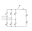
In order to protect converter, having known to provide with so-called " crowbar circuit " 90 to converter 7, and it is arranged and makes the rotor short circuit in winding where necessary, to absorb rotor current and to stop rotor current to enter the rotor inverter and damage its element.The exemplary of the basic layout of known crowbar circuit as shown in Figure 2.Basically, crowbar circuit comprises three branches that are arranged in parallel, and each branch comprises two diodes (91,92 that are connected in series; 93,94; 95,96).Between two diodes of each branch, there is a crowbar circuit to be connected to the tie point of corresponding rotor winding.What connect with three branches that comprise diode is the branch that comprises power scr 98 and resistor 97 (optional).Crowbar circuit is worked by following mode:
When normal operation, thyristor 98 is by locking, and making does not have electric current to flow through thyristor.Thereby, there is not electric current to flow through diode 91-96, rotor current all feeds back to the rotor inverter 71-73 of converter 7 by control circuit 8.Heighten the added-time when rotor current has, these electric currents make the PWM of the IGBT overload of rotor inverter and IGBT78 Be Controlled module 80 be stopped (work that is IGBT is stopped) (control module 80 is read the electric current I by control circuit 8
LValue and when described electric current exceeds certain level, be programmed to stop the work of IGBT).Rotor current then will flow through fly-wheel diode 79, thereby cause the voltage on the DC link 77 to increase.This increases by control module 80 and detects, in case and the voltage on the DC link reach predetermined threshold value, control module excites the power scr 98 of crowbar circuit, thereby allows electric current to flow through described thyristor.Thereafter, the high rotor electric current will begin to flow through the diode of crowbar circuit, rather than flows through the rotor inverter.When crowbar circuit is useed short circuit as, rotor voltage will approach zero.
Next, switch 6 is disconnected, thereby stator 2 is connected with the electrical network disconnection; Generator then will will be by degaussing on described switch 6 and crowbar circuit 90.Thereafter, in case line voltage has turned back to rated value, generator can be connected to electrical network once more.
Fig. 3 A-3G uses identical time shaft to show when producing short circuit in the electrical network, has the development of some parameters of Fig. 1 system of the prior art crowbar circuit of Fig. 2.Following time point is related to:
T1: the time when being short-circuited in the electrical network
T2: the time when crowbar circuit is triggered
T3: the time when generator is connected (by cut-off switch 6) with the electrical network disconnection
T4: the time when generator is reconnected to electrical network (by Closing Switch 6)
Fig. 3 A shows near U time t1 (time of short circuit in the electrical network)
GDecline.
Fig. 3 B shows stator current I
SAt t1, stator current begins to increase sharply and it kept high level always before time t3, when switch 6 is disconnected, thereby stator is connected (stator current is interrupted then) with the electrical network disconnection.Subsequently, in case the voltage on the electrical network is got back to its rated value, generator is reconnected to electrical network (at t4) and stator current begins to flow once more.
Fig. 3 C shows rotor current I
RHow to change its almost the same (because rotor and stator are as primary side and secondary side of transformer) with the mode of stator current.Unique difference is because the magnetizing current of generator is from rotor-side.Thereby, in Fig. 3 C, before t4, can find little very shortly magnetizing current.
Fig. 3 D shows the electric current (I from rotor to the rotor inverter
L).At t1, this rotor inverter current increase sharply (after rotor current increased, rotor current was all fed back to the rotor inverter).Rotor inverter Be Controlled module 80 stops and electric current then flows through fly-wheel diode 79 and flows into DC link.Voltage (U on the DC link
DC) (with reference to figure 3E) very fast increase, reach certain level up to it.Afterwards, to time t2, crowbar circuit Be Controlled module (it is just reading the voltage on the DC link) triggers.Then, rotor current is rectified to crowbar circuit (and almost drop to immediately zero, that is, do not have electric current to be fed back to the converter 7 from rotor).In case voltage is got back on the electrical network, the rotor inverter begins to provide magnetizing current to the rotor of generator, and and synchronized.After generator is connected to electrical network (at t4), rotor current is increased to rated value (with reference to figure 3C) (if enough wind energies are arranged) again.
In Fig. 3 E, how it shows at the t1 DC link by the quick charge (voltage U on the DC link
DCThereby increase).At t2, crowbar circuit is triggered and charges and is stopped.The discharge of DC link is finished by grid inverters.Grid inverters discharges into rated value (800V with DC link
DC).
Fig. 3 F shows the electric current I by crowbar circuit
CRBefore time t2, crowbar circuit is run into whole rotor currents.
At last, Fig. 3 G shows rotor voltage U
RWhen beginning, rotor voltage is in its operate as normal level.At t1, the rotor inverter be stopped and rectification after rotor voltage reach the level of DC link immediately.Rotor voltage increases with the voltage on the DC link, till crowbar circuit is triggered when t2; Afterwards, rotor is by short circuit, and rotor voltage drops to zero.In case switch is disconnected and generator is connected with the electrical network disconnection, crowbar circuit is disconnected once more.In case line voltage is got back to its rated value, the rotor inverter is by synchronously, and rotor voltage comes back to its operate as normal level.
Described in top example, generator and electrical network disconnect be connected be used traditionally when on electrical network, going wrong and because with network management relevant reason protection generator and converter (causing the rotor current surge) as short circuit.Traditionally, disconnect to connect the problem that is not regarded as yet including about any essence of the whole power supply of electrical network, because wind-driven generator only accounts for the very fraction (usually at below 5% of total power supply) of total power supply of electrical network.Yet, in many countries, wind power generation is just showing as the part of the quick increase of power generation, and in some country, wind power generation accounts for the pith of total generating, thereby if disconnects the serious problems that the connection of wind-driven generator can cause whole distributing electric power on the electrical network suddenly.
Therefore, need provide a kind of scheme, generator is disconnected with electrical network be connected and suitably work.
Yet, address in the prior art scheme of using crowbar circuit 90 protection converters 7 last, generator is disconnected with electrical network be connected, because the crowbar circuit that is triggered produces hard short circuit in rotor-side.Be not connected if stator disconnects with electrical network, the short circuit of rotor will produce stable overcurrent in rotor and stator winding.In normal work period, have specified line voltage and revolutional slip, rotor voltage is about 200Vrms.If if rotor is connected with the electrical network disconnection by short circuit and stator, then during long-time, the overcurrent that is three times in rated current usually will be arranged, if next crowbar circuit is disconnected connection, these overcurrent produce overvoltage with " jumping " in the rotor inverter and on DC link 77.Afterwards, crowbar circuit 90 will be triggered etc. once more.Basically, have no idea to avoid this circulation.Thereby for fear of these long overcurrent, stator must disconnect with electrical network and being connected.
Among the JP-A-07-067393 and JP-A-07-194196 that mentions in the above, the problem relevant with voltage decline in the electrical network solves by the chopper circuit of interpolation with the direct current transmission line parallel.Next, rotor current flows through the fly-wheel diode of rotor inverter and DC link is charged.When the voltage on the DC link rises and when being higher than predeterminated level, the chopper that is connected with resistor in series be activated and DC link on voltage limited by DC link is discharged.Yet this solution requirement is selected to support high electric current (because rotor current will continue to flow through the fly-wheel diode of rotor inverter) the fly-wheel diode of rotor inverter.In addition, the chopper needs can cut switch such as GTO or IGBT, i.e. active switch.In addition, because the protection reason must have crowbar circuit and rotor inverter to be connected in parallel.
Target of the present invention provides and stator and electrical network disconnected be connected the scheme that can protect converter, and it does not require the fly-wheel diode that virtually any size is excessive, and preferred option does not have active switch.Preferably, this scheme should not require any crowbar circuit.
Summary of the invention
A first aspect of the present invention relates to the control system of double fed induction generators (DFIG), comprise rotor and can be connected to electrical network to be used for the stator with stator winding of distributing electric power with rotor winding, described control system comprises converter, and described converter comprises following element:
Can be connected to the rotor inverter of the rotor winding of generator,
Can be connected to the grid inverters of electrical network and/or stator winding, and
The DC link that is used for feed rotor inverter.
According to the present invention; converter also comprises clamp units; be used for protecting converter to exempt from the infringement that the overcurrent owing to the rotor winding causes; described clamp units can be connected on the rotor winding and be arranged to and it occur after the overcurrent will trigger from non operating state and be operating state in detecting the rotor winding; described clamp units comprises clamp element; it is arranged to when clamp units during in its non operating state; electric current in the rotor winding can not pass through described clamp element; and during in its operating state, the electric current in the rotor winding can pass through described clamp element in clamp units.Clamp element comprises at least one passive piezoresistive element, and it is used for providing clamping voltage on the rotor winding.
Piezoresistive element can be selected so that for any desired value of the rotor current that occurs during grid short circuit, suitable clamping voltage will obtain at clamp element thereby on the rotor winding.Described clamping voltage is very important in preset range.Particularly, it should not be allowed to too low, will reduce (as long as stator remains connected to electrical network) very lentamente because too low clamping voltage means the electric current in the rotor winding.In fact, if clamping voltage is lower than the rotor voltage level of normal work period, then rotor current will drop to zero never.
And wish that rotor current reduces as quickly as possible, to allow converter to restart work, it is by means of making clamp units get back to its non operating state (rotor current is rectified to the rotor inverter again by this), thereby converter can be taken over the control of generator again.The control that converter can be taken over rotor current as early as possible is considered to very important, can be also can control the power output (this operator who is generally electrical network is required) to electrical network the short circuit on the electrical network duration.
Therefore, clamp element is that piezoresistive element is very important, thereby voltage will not be the pure linear function of rotor current: the use of general resistor means that clamping voltage directly is proportional to rotor current with (in fact).When selecting resistance, should note selecting the enough low resistance of resistance value to exceed the maximum horizontal of rotor voltage permission never to guarantee clamping voltage, can not exceed even flow through when the electric current of resistor reaches the high rotor levels of current of expection yet.Yet, if because the actual rotor electric current that the short circuit in the electrical network produces during far below the highest level of described expection, such low-resistance value will cause too low clamping voltage level.In this case, because too low clamping voltage, rotor current will can not reduce fast enough with the permission converter takes over control again, or at least can control as desired the adapter so fast.When specified rotor voltage, the use of low-resistance value resistor will cause the high stable state overcurrent in the rotor winding.
Yet,,, can select this element so that the quite clearly clamping voltage of definition to be provided, in suitable short range for possible rotor current in a big way by using piezoresistive element.In fact, have element that constant in fact clamping voltage can be provided the value of any rotor current level, described rotor current level consists essentially of because grid short circuit and the four corner of possible rotor current in very large scope.
Use passive piezoresistive element advantageous particularly,, and do not require the control of any complexity of clamp units because it provides the quite clearly clamping voltage of definition.Basically, it is enough to trigger clamp units to allow rotor current by clamp units rather than by the rotor inverter.Be used to trigger clamp units, can use simple triggering element such as power scr, it can be arranged to and be connected with corresponding rotor windings in series with clamp element and use low-down electric current to trigger (for example, below 1A, applying by simple pulse transformer) from control module.The clamp of the voltage on the rotor winding is realized by piezoresistive element itself, is not needed other control.That is, do not need " initiatively " to control this clamping voltage; In case below the rated value, control module can stop to trigger thyristor to stator current simply at it, thereby after next zero crossing of the electric current by thyristor, stop rotor current and flow through clamp units.
Clamp element can comprise a plurality of passive piezoresistive elements that are arranged in parallel, thereby allows very high rotor current to flow through clamp element, and can not damage single passive piezoresistive element.
(each) passive piezoresistive element can comprise:
-varistor (or a plurality of varistors that are connected in series);
-Zener diode (or a plurality of Zener diode that is connected in series); And/or
-inhibition diode (or a plurality of inhibition diode that is connected in series).
The example of suitable passive piezoresistive element is following element:
-varistor: from the BOK320 of manufacturer EPCOS
-suppress diode: from the BZW50-180 of manufacturer ST
-Zener diode: from the BZG05C100 of manufacturer Vishay
Each phase for rotor, clamp units can comprise the connector that is used to be connected to corresponding rotor phase, each connector is connected to trigger branch, and it comprises and being connected in series: clamp units to the tie point of connector being used to be connected to corresponding rotor phase; Be used to trigger the thyristor of clamp units; Clamp element; Diode; And the tie point that is connected to connector is to be used to be connected to corresponding rotor phase.Clamp units also can comprise the resistor that is connected in parallel with clamp element.
Clamp units can be arranged to trigger from non operating state and be operating state:
-when the rising of the voltage on the DC link is higher than predeterminated level (, the overcurrent in the rotor winding detects by the voltage of measuring on the DC link);
-when the rising of the voltage on the rotor winding is higher than predeterminated level (, the overcurrent in the rotor winding detects by the voltage of measuring on the rotor winding);
-when the rising of the electric current in the rotor winding is higher than predeterminated level (, the overcurrent in the rotor winding detects by the electric current of measuring in the rotor winding); And/or
When the rising of the electric current in the stator winding is higher than predeterminated level (, the overcurrent in the rotor winding detects by the electric current of measuring in the stator winding).
A second aspect of the present invention relates to double fed induction generators (DFIG) system, comprise rotor and can be connected to electrical network to be used for the stator with stator winding of distributing electric power with rotor winding, described doubly-fed induction generator system also comprises aforesaid control system, can be connected to the rotor inverter of the rotor winding of generator, can be connected to the grid inverters of electrical network, and be connected the clamp units on the rotor winding.
A third aspect of the present invention relates to and is used for the method for inverter that protection comprises the electricity generation system of double fed induction generators (DFIG) and control system; double fed induction generators comprises the rotor with rotor winding and can be connected to electrical network to be used for the stator with stator winding of distributing electric power; described control system comprises converter, described converter comprise the rotor winding that can be connected to generator the rotor inverter, can be connected to the grid inverters of electrical network and/or stator winding and be used for the DC link of feed rotor inverter.Described method comprises step:
The clamp units that will have clamp element is connected on the rotor winding, described clamp units comprises clamp element, it is arranged to make that the electric current in the rotor winding can not pass through described clamp element when clamp units is in non operating state, when clamp units during in its operating state, electric current in the rotor winding can pass through described clamp element, and described clamp element comprises that at least one passive piezoresistive element is to be used for providing clamping voltage on the rotor winding; And
When in the rotor winding, detecting overcurrent, clamp units is triggered to its operating state.
Clamp units can trigger from non operating state and be operating state, for example:
-when the rising of the voltage on the DC link is higher than predeterminated level,
-when the rising of the voltage on the rotor winding is higher than predeterminated level,
-when the rising of the electric current in the rotor winding is higher than predeterminated level, and/or
-when the rising of the electric current in the stator winding is higher than predeterminated level.
Description of drawings
Fig. 1 is the schematic diagram of DFIG of the prior art system.
Fig. 2 is the schematic diagram of crowbar circuit in the prior art.
Fig. 3 schematically showed during time interval after being short-circuited in electrical network, according to the variation of the partial parameters of prior art system.
Fig. 4 schematically showed during time interval after being short-circuited in electrical network, the variation of the partial parameters of system according to the preferred embodiment of the invention.
Fig. 5 is the schematic diagram of system according to the preferred embodiment of the invention.
Fig. 6 is the schematic diagram of the system of another preferred embodiment according to the present invention.
Fig. 7 is the schematic diagram of clamp units according to the preferred embodiment of the invention.
Embodiment
Fig. 5 and Fig. 6 show two preferred embodiments of the present invention.Element shown in the great majority is all fully corresponding to those elements with reference to figure 1 described prior art systems; These elements have identical Reference numeral and do not need other description.Yet, the converter 7 of replacement Fig. 2, Fig. 5 and 6 shows the converter that comprises identical primary element, and the two difference is:
In the converter shown in Fig. 5 170, crowbar circuit is substituted by clamp units 190, and converter comprises the control module 180 (in addition, control module 180 is moved like that by the control module 80 of the system of Fig. 1) that is suitable for controlling described clamp units;
And
In converter shown in Figure 6 171, clamp units 190 has been combined and has been connected in parallel with crowbar circuit 90, converter comprises the control module 181 (in addition, control module 181 is moved like that by the control module 80 of the system of Fig. 1) that is suitable for controlling described clamp units and crowbar circuit.
Fig. 7 shows the preferred embodiment of clamp units, and clamp units comprises that for each phase of rotor, connector 300 is used to be connected to corresponding rotor phase.Each connector is connected to trigger branch, and it comprises and being connected in series: clamp units to the tie point 297 of connector 300 being used for the corresponding rotor phase of tie point; Be used to trigger the thyristor 295 of clamp units; Clamp element 290; Diode 296; And the tie point 297 that is connected to connector 300 is to be used to be connected to corresponding rotor phase.
(can use thyristor to replace diode 296, its advantage is: than using diode, use thyristor to make to trigger the time delay that stopping and flowing through between actual the stopping of electric current of clamp units of clamp units to be lowered up to 50%).
Fig. 4 A shows line voltage, and short circuit occurs near t11.Afterwards, stator current I
S(Fig. 4 B) increases sharply.Yet in this case, generator is not disconnected and connects and will be by degaussing on stator and rotor current, and stator and rotor current will reduce then.In case stator current is lower than near nominal level (greatly t13), Be Controlled module 180,181 is disconnected clamp units 190 and rotor current will flow into the rotor inverter again.Converter is measured rotor current (by measuring the electric current I in the control circuit
L) and with the synchronous PWM of those electric currents.Rotor inverter control rotor current also provides constant rotor and stator current (in Fig. 4 B and 4C from t14 to t15) duration of remaining short circuit.Subsequently, when line voltage turns back to its rated value, thereby generator is not enough magnetized and high electric current flows to stator generation overcurrent (in the interval among Fig. 4 C between t15 and t17) from electrical network.Afterwards, the rotor inverter is stopped once more, and generator will be magnetized from electrical network.Thereafter, stator current reduces, in case its under rated value (t17), clamp units 190 is disconnected, and the rotor inverter is taken over the control of rotor current again.
Rotor current I
R(Fig. 4 C) is almost the same with stator current.
Fig. 4 D shows the electric current 1 (i.e. electric current from the rotor to the converter) of rotor inverter.At t11, rotor current increases sharply, at t12, and clamp units 190 be triggered (being triggered) as crowbar circuit in the above-mentioned prior art systems.Therefore, rotor current is rectified in the clamp units 190 and I
LDrop to zero.In case stator current drops to rated current following (t13), clamp units Be Controlled module 180,181 disconnects, and rotor current is rectified in the rotor inverter.Rotor inverter and rotor current (t14-t15) Control current synchronously and duration of remaining short circuit.(between t14 and t15, electric grid operating person requires wind turbine actively to power in the short circuit of wind turbine outside, to cause the connection that disconnects short circuit more quickly by the primary cut-out that disconnects in the electrical network.Especially for this purpose, all should Be Controlled at most of duration generators of short circuit.The present invention allows the rotor inverter only to be stopped in transit time, changes the appearance of the dynamic overcurrent that causes transit time corresponding to quick voltage on the electrical network).
When line voltage turns back to its rated value (t15), rotor current increases sharply, and the rotor inverter is stopped (when control module measures overcurrent) once more, and clamp units 190 is triggered and suffers rotor current.When stator current drops to nominal level when following (t17), clamp units is disconnected, and rotor current is rectified in the rotor inverter once more.The rotor current of rotor inverter and reality is synchronous and begin to rerun the control rotor current.
Fig. 4 E shows the voltage on the DC link.At t11, first spiking is arranged, it triggers clamp units 190 (at t12).Subsequently, as mentioned above, clamp units is disconnected and rotor current is rectified in the rotor inverter again, begin to charge once more DC link (t13), till the control of rotor inverter adapter rotor current (this is undertaken by control module 180,181, to take over the control of generator once more).This has taken place twice in Fig. 4 E, is because the voltage on the electrical network descends for the first time, is when line voltage rises once more for the second time.
Fig. 4 F shows clamp current I
CL(by the electric current of clamp units).As described above, clamp units suffers whole rotor currents for twice.
Fig. 4 G shows rotor voltage U
R
In beginning, rotor voltage is in its operate as normal level.Near t11, rotor current increases, and the rotor inverter is stopped.Rotor current flows into DC link 77 just as current source and on fly-wheel diode 79.At this, rotor voltage will with the same level of voltage on the DC link.
Rotor voltage increases with the increase of DC link voltage, and at t12, clamp units is triggered, and rotor voltage is clamped to the level consistent with the characteristic of selected clamp element 290.At t13, clamp units is disconnected, and rotor current flows into the rotor inverter, and rotor voltage jumps to the level of DC link voltage.After lock in time, the rotor inverter is started working (t14), and the level of rotor voltage is got back to the level corresponding to operate as normal at rotor inverter and actual rotor current.When short circuit condition keeps on electrical network (t14-t15), because the decline of stator voltage, " normally " voltage is lower than the voltage before the t11.
When voltage turns back to electrical network (t15), system will react according to voltage drop:
Near t15, the rotor current fast rise, and the rotor inverter is stopped; Rotor voltage is increased to the level of DC link voltage;
Near t16, clamp units is triggered, and rotor voltage is clamped to the level of being determined by the characteristic of clamp element 290;
Near t17, clamp units is disconnected, and rotor current flows into the rotor inverter, and rotor voltage jumps to the DC link voltage levvl;
At last, after lock in time, near t18, the rotor inverter restarts work at rotor inverter and actual rotor current.
Fig. 4 H shows clamping voltage U
CLIdeally, clamping voltage will change between two levels that clearly define, promptly between the zero-sum clamp level.
In whole specification and claims, speech " comprise " all do not mean get rid of that other is additional, element, integral body or step.
Claims (17)
1. the control system of double fed induction generators comprises the rotor (1) with rotor winding and is connected to electrical network to be used for the stator with stator winding (2) of distributing electric power;
Described control system comprises converter (170,171), and described converter comprises following element:
Be connected to the rotor inverter (71-73) of the rotor winding of generator,
Be connected to the grid inverters (74-76) of electrical network and/or stator winding, and
The DC link (77) that is used for feed rotor inverter;
Converter (170,171) also comprises clamp units (190); be used for protecting converter to exempt from the infringement that the overcurrent owing to the rotor winding causes; described clamp units (190) is connected on the rotor winding and is arranged to and occurs being operating state from the non operating state triggering after the overcurrent in detecting the rotor winding; described clamp units comprises clamp element (290), and described clamp element is arranged to feasible
When clamp units during in non operating state, the electric current in the rotor winding can not pass through described clamp element, and
When clamp units in working order the time, the electric current in the rotor winding is by described clamp element,
Described clamp element comprises at least one passive piezoresistive element (291,292,293,294), and described at least one passive piezoresistive element is used for providing clamping voltage on the rotor winding.
2. according to the control system of claim 1, wherein clamp element (290) comprises a plurality of passive piezoresistive elements that are connected in parallel (291,292,293,294).
3. according to the control system of claim 1 or 2, wherein said at least one passive piezoresistive element comprises at least one varistor.
4. according to the control system of claim 1 or 2, wherein said at least one passive piezoresistive element comprises at least one Zener diode.
5. according to the control system of claim 1 or 2, wherein said at least one passive piezoresistive element comprises at least one inhibition diode.
6. according to the control system of claim 5, wherein for each phase of rotor, clamp units comprises the connector (300) that is used to be connected to the respective rotor phase place, each connector is connected to trigger branch, trigger branch comprises the following part that is connected in series: the thyristor (295) that is used to trigger clamp units, clamp element (290) and diode (296), described connector (300) has the tie point (297) that is used to be connected to trigger branch, described tie point (297) is connected to the anode of thyristor (295), the negative electrode of thyristor (295) is connected with an end of clamp element (290), the other end of clamp element (290) is connected with the anode of diode (296), and the negative electrode of diode (296) is connected with described tie point (297).
7. according to the control system of claim 6, wherein clamp units also comprises the resistor (298) that is connected in parallel with clamp element (290).
8. according to the control system of claim 7, wherein clamp units is arranged to be operating state from the non operating state triggering when the rising of the voltage on the DC link is higher than predeterminated level.
9. according to the control system of claim 7, wherein clamp units is arranged to be operating state from the non operating state triggering when the rising of the voltage on the rotor winding is higher than predeterminated level.
10. according to the control system of claim 7, wherein clamp units is arranged to be operating state from the non operating state triggering when the rising of the electric current in the rotor winding is higher than predeterminated level.
11. according to the control system of claim 7, wherein clamp units is arranged to be operating state from the non operating state triggering when the rising of the electric current in the stator winding is higher than predeterminated level.
12. doubly-fed induction generator system, comprise rotor (1) and be connected to electrical network to be used for the stator with stator winding (2) of distributing electric power with rotor winding, described doubly-fed induction generator system also comprises arbitrary described control system according to claim 1-11, wherein
Rotor inverter (71-73) is connected to the rotor winding of generator,
Grid inverters (74-76) is connected to electrical network, and
Clamp units (190) is connected on the rotor winding.
13. be used for protecting the method for the converter of the electricity generation system that comprises double fed induction generators and control system, double fed induction generators comprises the rotor (1) with rotor winding and is connected to electrical network to be used for the stator with stator winding (2) of distributing electric power, control system comprises converter (170,171), described converter comprise the rotor winding that is connected to generator rotor inverter (71-73), be connected to the grid inverters (74-76) of electrical network and/or stator winding and be used for the DC link (77) of feed rotor inverter;
By this, described method comprises step:
The clamp units (190) that will have clamp element is connected on the rotor winding, described clamp units comprises clamp element (290), clamp element is arranged to make: the electric current when clamp units is in non operating state in the rotor winding can not pass through described clamp element, and when clamp units in working order the time electric current in the rotor winding pass through described clamp element; Described clamp element comprises that at least one passive piezoresistive element (291,292,293,294) is to be used for providing clamping voltage on the rotor winding; And
When in the rotor winding, detecting overcurrent, clamp units is triggered to operating state from non operating state.
14. according to the method for claim 13, wherein clamp units is an operating state by triggering from non operating state when the rising of the voltage on the DC link is higher than predeterminated level.
15. according to the method for claim 13, wherein clamp units is an operating state by triggering from non operating state when the rising of the voltage on the rotor winding is higher than predeterminated level.
16. according to the method for claim 13, wherein clamp units is an operating state by triggering from non operating state when the rising of the electric current in the rotor winding is higher than predeterminated level.
17. according to the method for claim 13, wherein clamp units is an operating state by triggering from non operating state when the rising of the electric current in the stator winding is higher than predeterminated level.
Applications Claiming Priority (2)
| Application Number | Priority Date | Filing Date | Title |
|---|---|---|---|
| EP20030380174 EP1499009B1 (en) | 2003-07-15 | 2003-07-15 | Control and protection of a doubly-fed induction generator system |
| EP03380174.7 | 2003-07-15 |
Publications (2)
| Publication Number | Publication Date |
|---|---|
| CN1823467A CN1823467A (en) | 2006-08-23 |
| CN100424988C true CN100424988C (en) | 2008-10-08 |
Family
ID=33462270
Family Applications (1)
| Application Number | Title | Priority Date | Filing Date |
|---|---|---|---|
| CNB2004800198515A Active CN100424988C (en) | 2003-07-15 | 2004-07-01 | Control and protection of a doubly-fed induction generator system |
Country Status (8)
| Country | Link |
|---|---|
| US (1) | US7518256B2 (en) |
| EP (1) | EP1499009B1 (en) |
| KR (1) | KR100832769B1 (en) |
| CN (1) | CN100424988C (en) |
| AT (1) | ATE377286T1 (en) |
| DE (1) | DE60317183T2 (en) |
| PT (1) | PT1499009E (en) |
| WO (1) | WO2005015730A1 (en) |
Cited By (4)
| Publication number | Priority date | Publication date | Assignee | Title |
|---|---|---|---|---|
| CN102231529A (en) * | 2011-06-07 | 2011-11-02 | 北京交通大学 | Method for controlling switchover-free grid connection of double-fed wind driven generator |
| TWI415384B (en) * | 2011-09-07 | 2013-11-11 | Delta Electronics Shanghai Co | Wind-power generation system with over-speed protection and method for operating the same |
| CN103683318A (en) * | 2012-08-31 | 2014-03-26 | 通用电气公司 | System and method for controlling dual-fed induction generator in response to high-voltage grid events |
| CN105339653A (en) * | 2013-06-24 | 2016-02-17 | 乌本产权有限公司 | Wind turbine |
Families Citing this family (112)
| Publication number | Priority date | Publication date | Assignee | Title |
|---|---|---|---|---|
| CN100353055C (en) * | 2001-04-20 | 2007-12-05 | 阿洛伊斯·沃本 | Method for operating a wind energy plant |
| DE10119624A1 (en) | 2001-04-20 | 2002-11-21 | Aloys Wobben | Operating wind energy plant involves regulating power delivered from generator to electrical load, especially of electrical network, depending on current delivered to the load |
| DE10327344A1 (en) * | 2003-06-16 | 2005-01-27 | Repower Systems Ag | Wind turbine |
| GB2420456A (en) * | 2004-11-23 | 2006-05-24 | Areva T & D Uk Ltd | Generator control having grid imbalance detector |
| AU2004326154B2 (en) * | 2004-12-28 | 2009-03-19 | Vestas Wind Systems A/S | Method of controlling a wind turbine connected to an electric utility grid |
| US7215035B2 (en) * | 2005-02-22 | 2007-05-08 | Xantrex Technology, Inc. | Method and apparatus for converting wind generated electricity to constant frequency electricity for a utility grid |
| US7239036B2 (en) * | 2005-07-29 | 2007-07-03 | General Electric Company | System and method for power control in wind turbines |
| EP1752660B1 (en) * | 2005-08-12 | 2013-04-03 | General Electric Company | Wind turbine over-voltage protection |
| WO2007035411A2 (en) * | 2005-09-16 | 2007-03-29 | Satcon Technology Corporation | Slip-controlled, wound-rotor induction machine for wind turbine and other applications |
| DE102005051753A1 (en) * | 2005-10-27 | 2007-05-24 | Suzlon Energy Gmbh | Circuit arrangement for switching off a crowbar |
| ES2296483B1 (en) * | 2005-11-21 | 2009-03-01 | Ingeteam Technology, S.A. | A CONTROL AND PROTECTION SYSTEM BEFORE SYMBOLIC AND ASYMETRIC FAULTS, FOR ASYNCHRONOUS GENERATORS. |
| US7253537B2 (en) | 2005-12-08 | 2007-08-07 | General Electric Company | System and method of operating double fed induction generators |
| ES2291103B1 (en) * | 2005-12-30 | 2009-02-01 | Universidad Publica De Navarra | CONVERTER CONTROL METHOD AND SYSTEM OF AN ELECTRICAL GENERATION INSTALLATION CONNECTED TO AN ELECTRICAL NETWORK BEFORE THE PRESENCE OF VOLTAGE HOLES IN THE NETWORK. |
| ES2298014B1 (en) * | 2005-12-30 | 2009-07-23 | Universidad Publica De Navarra | METHOD AND SYSTEM FOR THE PROTECTION OF AN ELECTRICAL GENERATION INSTALLATION CONNECTED TO AN ELECTRICAL NETWORK BEFORE THE PRESENCE OF VOLTAGE HOLES IN THE NETWORK. |
| US7816801B2 (en) * | 2006-03-16 | 2010-10-19 | International Components Corporation, Inc. | Speed sensing circuit for a wind turbine generator |
| US7425771B2 (en) | 2006-03-17 | 2008-09-16 | Ingeteam S.A. | Variable speed wind turbine having an exciter machine and a power converter not connected to the grid |
| CN101401294B (en) * | 2006-03-17 | 2013-04-17 | 英捷电力技术有限公司 | Variable speed wind turbine having an exciter machine and a power converter not connected to the grid |
| DE102006018160A1 (en) * | 2006-04-19 | 2007-10-25 | Siemens Ag | Rectifier cascade-arrangement for use in speed-changeable drive system, has transformer for feeding energy back into network, and rectifier having insulated-gate bipolar transistors functioning as power semiconductor switches |
| WO2007140466A2 (en) * | 2006-05-31 | 2007-12-06 | Wisconsin Alumni Research Foundation | Power conditioning architecture for a wind turbine |
| CN100456628C (en) * | 2006-10-26 | 2009-01-28 | 天津理工大学 | AC exciting control system of double feed wind power generator based on DSP with secondary frequency modulation and its working method |
| DE102006051546A1 (en) * | 2006-11-02 | 2008-05-08 | Nordex Energy Gmbh | Method for operating a wind turbine with a double-fed asynchronous generator and wind turbine with a double-fed asynchronous generator |
| WO2008077974A1 (en) * | 2006-12-22 | 2008-07-03 | Wind To Power System, S.L. | Asynchronous generator with double supply |
| EP2128440A4 (en) * | 2006-12-28 | 2012-03-14 | Wind To Power System S L | Asynchronous generator with control of the voltage applied to the stator |
| US7622815B2 (en) * | 2006-12-29 | 2009-11-24 | Ingeteam Energy, S.A. | Low voltage ride through system for a variable speed wind turbine having an exciter machine and a power converter not connected to the grid |
| US7615904B2 (en) * | 2007-01-24 | 2009-11-10 | Raven Energy Alternatives, Llc | Brushless high-frequency alternator and excitation method for three-phase AC power-frequency generation |
| CN101033730B (en) * | 2007-01-25 | 2010-06-02 | 上海交通大学 | Control method for stably operating wind power field using double-fed asynchronous generator |
| JP2008306776A (en) * | 2007-06-05 | 2008-12-18 | Hitachi Ltd | Wind power generation system and control method thereof |
| KR100886194B1 (en) | 2007-06-08 | 2009-02-27 | 한국전기연구원 | Controller of double-fed induction generator |
| DE102007032179A1 (en) * | 2007-07-10 | 2009-01-22 | Repower Systems Ag | Wind turbine with extended speed range |
| US8044527B2 (en) * | 2007-09-26 | 2011-10-25 | General Electric Company | Electric power generation with magnetically geared machine |
| WO2009043943A1 (en) * | 2007-10-01 | 2009-04-09 | Ingeteam Energy, S.A. | Method for coupling and controlling reactive power by means of a stator for doubly-fed wind turbines for use in any wind conditions |
| US7884492B2 (en) * | 2007-11-13 | 2011-02-08 | General Electric Company | Methods and systems for wind turbine generators |
| JP4845904B2 (en) * | 2008-02-08 | 2011-12-28 | 株式会社日立製作所 | Wind power generation system |
| DE102008034532A1 (en) * | 2008-02-20 | 2009-08-27 | Repower Systems Ag | Wind turbine with inverter control |
| DE102008017715A1 (en) * | 2008-04-02 | 2009-10-15 | Nordex Energy Gmbh | Method for operating a wind turbine with a double-fed asynchronous machine and wind turbine with a double-fed asynchronous machine |
| ITTO20080324A1 (en) * | 2008-04-30 | 2009-11-01 | Trevi Energy S P A | MODULAR ELECTRICAL POWER CONVERTER PRODUCED BY WIND GENERATORS AND WIND POWER PLANT EMPLOYING THE SAME. |
| ES2360433B1 (en) * | 2008-05-23 | 2012-04-20 | Ingeteam S.A. | METHOD AND CONTROL SYSTEM OF A WIND INSTALLATION BEFORE NETWORK FAULTS. |
| ES2331285B1 (en) * | 2008-06-26 | 2010-09-27 | Ingeteam Energy, S.A. | METHOD OF CONTROL OF A WIND TURBINE. |
| US7944068B2 (en) * | 2008-06-30 | 2011-05-17 | General Electric Company | Optimizing converter protection for wind turbine generators |
| DE102008032876B4 (en) * | 2008-07-14 | 2010-04-08 | Sew-Eurodrive Gmbh & Co. Kg | Method, circuit arrangement and bridge circuit |
| EP2161821B1 (en) * | 2008-09-03 | 2020-06-17 | General Electric Company | Magnetically geared generator |
| US7741729B2 (en) * | 2008-10-15 | 2010-06-22 | Victor Lyatkher | Non-vibrating units for conversion of fluid stream energy |
| WO2010045964A1 (en) * | 2008-10-20 | 2010-04-29 | Woodward Seg Gmbh & Co. Kg | Protection system of a doubly-fed induction machine |
| DE102008064078A1 (en) * | 2008-12-19 | 2010-06-24 | Converteam Technology Ltd., Rugby | Method for starting a double-fed asynchronous machine |
| WO2010082317A1 (en) * | 2009-01-14 | 2010-07-22 | 東芝三菱電機産業システム株式会社 | Protection circuit used in wind power generation system including double-fed induction generator |
| CN101521481B (en) * | 2009-04-07 | 2011-01-12 | 浙江大学 | Asymmetry coordination direct power control method of double-fed asynchronous wind power generation system |
| CH701753A1 (en) * | 2009-09-03 | 2011-03-15 | Ids Holding Ag | Speed variable generator system for use in e.g. hydro power plant, has voltage limiter attached at secondary side of generator such that secondary sided current is derived during high current through frequency converter |
| CH701746A2 (en) | 2009-09-03 | 2011-03-15 | Ids Holding Ag | Generator system with direct netzgekoppeltem generator and method for driving through grid disturbances. |
| US7843078B2 (en) * | 2009-09-30 | 2010-11-30 | General Electric Company | Method and apparatus for generating power in a wind turbine |
| US8860236B2 (en) * | 2009-10-19 | 2014-10-14 | Uwm Research Foundation, Inc. | Wind energy power conversion system reducing gearbox stress and improving power stability |
| US8018082B2 (en) * | 2009-11-25 | 2011-09-13 | General Electric Company | Method and apparatus for controlling a wind turbine |
| KR101103665B1 (en) | 2009-12-16 | 2012-01-11 | 한국전기연구원 | In-phase method for generation system with doubly-fed induction generator |
| CN101741100A (en) * | 2010-01-11 | 2010-06-16 | 华锐风电科技(集团)股份有限公司 | Low voltage ride-through control scheme |
| AT509838A2 (en) * | 2010-03-19 | 2011-11-15 | Moeller Gebaeudeautomation Gmbh | FAULT CIRCUIT BREAKER |
| TWI420772B (en) * | 2010-04-06 | 2013-12-21 | Szu Lin Liu | Wind-powered output power regulating circuit |
| CN101895128B (en) * | 2010-07-02 | 2013-04-10 | 国网电力科学研究院 | Control method of voltage fluctuation feedback of grid-connected current transformer under asymmetric voltage |
| CN101917130B (en) * | 2010-08-05 | 2012-07-18 | 国电南京自动化股份有限公司 | Quick energy response method for grid-side converter in DFIG (Doubly-Fed Induction Generator) low-voltage ride-through (LVRT) process |
| US8471534B2 (en) * | 2010-08-26 | 2013-06-25 | General Electric Company | Fault ride through switch for power generation system |
| EP2621071A4 (en) * | 2010-09-22 | 2017-05-17 | Toshiba Mitsubishi-Electric Industrial Systems Corporation | Power conversion device |
| US9184685B2 (en) | 2010-10-28 | 2015-11-10 | Vestas Wind Systems A/S | Wind turbine generator |
| KR101243181B1 (en) * | 2010-11-04 | 2013-03-14 | 한국전기연구원 | Control Device for a doubly-fed induction generator in which feedback linearization method is embedded |
| ES2654595T3 (en) | 2010-11-11 | 2018-02-14 | Ingeteam Power Technology, S.A. | Power converter control procedure |
| EP2463976A1 (en) * | 2010-12-08 | 2012-06-13 | Siemens Aktiengesellschaft | Circuit and method for regulating a DC voltage and power con-verter |
| GB2483524B (en) * | 2011-01-27 | 2012-08-08 | Protean Electric Ltd | A switch arrangement |
| DE102011000459B4 (en) * | 2011-02-02 | 2017-11-02 | Universität Kassel | Method for supplying reactive current with a converter and converter arrangement and energy supply system |
| DE102011001786A1 (en) * | 2011-04-04 | 2012-10-04 | Woodward Kempen Gmbh | Control cabinet arrangement of a device for generating electrical energy |
| DE102011076925A1 (en) * | 2011-06-03 | 2012-12-06 | Siemens Aktiengesellschaft | Asynchronous electrical machine i.e. doubly fed asynchronous machine, for use in machine nacelle of wind power plant, has switchable short circuit path formed between rectifier bridge and inverter for short circuiting converter |
| FR2977738B1 (en) * | 2011-07-04 | 2015-01-16 | Mersen France Sb Sas | CONTINUOUS CURRENT INTERRUPTION SYSTEM FOR OPENING INDUCTIVE CONTINUOUS CURRENT LINE |
| DE102011051732B3 (en) * | 2011-07-11 | 2013-01-17 | Pcs Power Converter Solutions Gmbh | Wind turbine |
| CN102901919B (en) | 2011-07-29 | 2015-02-04 | 台达电子企业管理(上海)有限公司 | Double-feedback type induction generating system and self-testing method of active crowbar circuit thereof |
| US20130057227A1 (en) * | 2011-09-01 | 2013-03-07 | Ingeteam Technology, S.A. | Method and apparatus for controlling a converter |
| US9041234B2 (en) | 2012-03-26 | 2015-05-26 | Rockwell Automation Technologies, Inc. | Double fed induction generator (DFIG) converter and method for improved grid fault ridethrough |
| CN102769305A (en) * | 2012-07-12 | 2012-11-07 | 华北电力大学 | Boiler smoke waste heat power generation system |
| WO2014008647A1 (en) * | 2012-07-12 | 2014-01-16 | General Electric Company | Dynamic braking system for an electric power system and method of operating the same |
| US8664788B1 (en) * | 2012-09-07 | 2014-03-04 | General Electric Company | Method and systems for operating a wind turbine using dynamic braking in response to a grid event |
| US8669669B1 (en) * | 2012-09-13 | 2014-03-11 | General Electric Company | Voltage control in a doubly-fed induction generator wind turbine system |
| WO2014107802A1 (en) * | 2013-01-14 | 2014-07-17 | The Governors Of The University Of Alberta | Grid-connected induction machine with controllable power factor |
| US8941961B2 (en) | 2013-03-14 | 2015-01-27 | Boulder Wind Power, Inc. | Methods and apparatus for protection in a multi-phase machine |
| DE102013208544A1 (en) * | 2013-05-08 | 2014-11-13 | Lenze Drives Gmbh | drive system |
| US9048764B2 (en) * | 2013-05-29 | 2015-06-02 | General Electric Company | Connection for improved current balancing in a parallel bridge power converter |
| DK3004637T4 (en) | 2013-06-04 | 2021-02-15 | Gen Electric | METHODS FOR OPERATING WIND TURBINE SYSTEM WITH DYNAMIC BRAKE |
| US8975768B2 (en) | 2013-06-05 | 2015-03-10 | General Electic Company | Methods for operating wind turbine system having dynamic brake |
| EP2944019B1 (en) * | 2013-08-30 | 2016-07-20 | ABB Technology AG | Electric unit for a pump-storage power plant |
| US20150084439A1 (en) * | 2013-09-23 | 2015-03-26 | General Electric Company | Shorting assembly and method for wind turbine power supply |
| US9614457B2 (en) | 2013-10-18 | 2017-04-04 | Abb Schweiz Ag | Modular thyristor-based rectifier circuits |
| US9334749B2 (en) | 2013-10-18 | 2016-05-10 | Abb Technology Ag | Auxiliary power system for turbine-based energy generation system |
| US9577557B2 (en) * | 2013-10-18 | 2017-02-21 | Abb Schweiz Ag | Turbine-generator system with DC output |
| EP3063851B1 (en) * | 2013-10-31 | 2021-12-22 | General Electric Company | System and method for controlling wind power generation systems |
| US9231509B2 (en) | 2013-11-25 | 2016-01-05 | General Electric Company | System and method for operating a power generation system within a power storage/discharge mode or a dynamic brake mode |
| US10352304B2 (en) * | 2013-12-18 | 2019-07-16 | Ingeteam Power Technology, S.A. | Variable impedance device for a wind turbine |
| US9337685B2 (en) | 2013-12-23 | 2016-05-10 | General Electric Company | Optimized filter for battery energy storage on alternate energy systems |
| JP6071912B2 (en) * | 2014-01-27 | 2017-02-01 | 株式会社東芝 | Overvoltage protection device and current adjustment circuit |
| JP6158109B2 (en) * | 2014-02-07 | 2017-07-05 | 株式会社東芝 | Overvoltage protection device |
| DE102014202771A1 (en) * | 2014-02-14 | 2015-08-20 | Sirona Dental Systems Gmbh | Control circuit and control method for synchronous machine |
| CN106575936A (en) * | 2014-07-02 | 2017-04-19 | 通用电气能源能量变换技术有限公司 | Overvoltage protection self-trigger circuit for double fed induction generator (dfig) wind power system |
| CN105790298B (en) * | 2014-12-23 | 2019-03-12 | 台达电子工业股份有限公司 | Wind power generation controlling device and wind generator system |
| US9705440B2 (en) * | 2015-07-16 | 2017-07-11 | Hamilton Sundstrand Corporation | Fault tolerant electric power generating system |
| DE102015009742A1 (en) * | 2015-07-31 | 2017-02-02 | Senvion Gmbh | Internal demand control for a wind energy plant |
| US9945359B2 (en) * | 2015-08-13 | 2018-04-17 | Abb Schweiz Ag | DC output wind turbine with power dissipation |
| DK3157161T3 (en) * | 2015-10-12 | 2019-05-20 | Siemens Ag | WIND POWER INSTALLATION PROCEDURE |
| EP3200331B1 (en) * | 2016-01-27 | 2019-11-20 | GE Energy Power Conversion Technology Ltd | Method to protect a power converter arrangement and power converter arrangement with a protective device |
| US9847733B2 (en) | 2016-05-12 | 2017-12-19 | Rockwell Automation Technologies, Inc. | Power conversion system with DC bus regulation for abnormal grid condition ride through |
| CN107681684B (en) * | 2016-08-02 | 2021-05-07 | 台达电子企业管理(上海)有限公司 | Medium-voltage wind power generation system and power generation method thereof |
| US10630215B2 (en) * | 2017-11-20 | 2020-04-21 | General Electric Company | System and method for operating a doubly fed induction generator system to reduce harmonics |
| EP3506449A1 (en) * | 2017-12-29 | 2019-07-03 | Acciona Windpower, S.A. | Method for operating electrical machines |
| CN110080944B (en) * | 2018-01-26 | 2021-09-24 | 通用电气公司 | Wind power generation system and control method thereof |
| CN110912179A (en) * | 2018-09-14 | 2020-03-24 | 中车株洲电力机车研究所有限公司 | Fault-tolerant control method of double-fed wind turbine generator, double-fed wind turbine generator and double-fed motor |
| US11394324B2 (en) | 2019-12-17 | 2022-07-19 | General Electric Company | Selective crowbar response for a power converter to mitigate device failure |
| KR20210090908A (en) * | 2020-01-13 | 2021-07-21 | 엘지전자 주식회사 | A Motor Assembly And The Controlling Method Thereof |
| US11843325B2 (en) | 2020-08-24 | 2023-12-12 | General Electric Company | Crowbar module for an active neutral point clamped power conversion assembly |
| US11486355B2 (en) * | 2020-12-31 | 2022-11-01 | General Electric Company | Method for operating doubly-fed wind turbine generator as a virtual synchronous machine to provide grid-forming control thereof |
| CN113236525B (en) * | 2021-06-11 | 2022-08-30 | 西安热工研究院有限公司 | Method for transforming steam-driven water-feeding pump into double-fed motor-driven water-feeding pump and starting method |
Citations (5)
| Publication number | Priority date | Publication date | Assignee | Title |
|---|---|---|---|---|
| CA1124781A (en) * | 1978-10-31 | 1982-06-01 | James C. Murdoch | Control circuit for discharging the field winding of a synchronous motor |
| US4812729A (en) * | 1986-08-19 | 1989-03-14 | Hitachi Ltd. | Protecting apparatus for secondary excitation type variable speed AC generator/motor |
| JPH07194196A (en) * | 1993-12-27 | 1995-07-28 | Toshiba Corp | Controller for wire-wound induction machine |
| US5734256A (en) * | 1995-05-31 | 1998-03-31 | General Electric Company | Apparatus for protection of power-electronics in series compensating systems |
| DE19735742A1 (en) * | 1997-08-18 | 1999-02-25 | Siemens Ag | Current regulator cascade with asynchronous machine |
Family Cites Families (20)
| Publication number | Priority date | Publication date | Assignee | Title |
|---|---|---|---|---|
| US3894274A (en) * | 1974-07-01 | 1975-07-08 | Gen Electric | Electric motor transient voltage suppressing circuit |
| SE392010B (en) | 1976-02-27 | 1977-03-07 | Ericsson Telefon Ab L M | NET FOR COMPENSATION OF LOSS DAMPING TEMPERATURE DEVIATION IN A PASSIVE FILTER |
| SE449151B (en) | 1983-06-17 | 1987-04-06 | Asea Ab | PROTECTIVE DEVICE FOR A SERIES CONDENSER |
| JP3026474B2 (en) | 1993-04-07 | 2000-03-27 | 株式会社東芝 | Semiconductor integrated circuit |
| JP3100805B2 (en) * | 1993-08-24 | 2000-10-23 | 東京電力株式会社 | Overvoltage protection device for variable speed pumped storage power generation system |
| US5798631A (en) * | 1995-10-02 | 1998-08-25 | The State Of Oregon Acting By And Through The State Board Of Higher Education On Behalf Of Oregon State University | Performance optimization controller and control method for doubly-fed machines |
| US6600240B2 (en) * | 1997-08-08 | 2003-07-29 | General Electric Company | Variable speed wind turbine generator |
| US6137187A (en) * | 1997-08-08 | 2000-10-24 | Zond Energy Systems, Inc. | Variable speed wind turbine generator |
| US6226166B1 (en) * | 1997-11-28 | 2001-05-01 | Erico Lighting Technologies Pty Ltd | Transient overvoltage and lightning protection of power connected equipment |
| FR2798784B1 (en) * | 1999-09-17 | 2002-01-11 | Francois Girard | OVERVOLTAGE PROTECTION DEVICE |
| WO2002061910A2 (en) * | 2001-01-31 | 2002-08-08 | Satcon Technology Corporation | Uninterruptible power supply system |
| CA2472144C (en) * | 2002-01-29 | 2010-09-28 | Vestas Wind Systems A/S | Circuit arrangement for use in a wind energy installation |
| DE10206828A1 (en) * | 2002-01-29 | 2003-08-14 | Lorenz Feddersen | Circuit arrangement for use in a wind turbine |
| US7015595B2 (en) * | 2002-02-11 | 2006-03-21 | Vestas Wind Systems A/S | Variable speed wind turbine having a passive grid side rectifier with scalar power control and dependent pitch control |
| US6943531B2 (en) * | 2002-03-20 | 2005-09-13 | Yamaha Hatsudoki Kabushiki Kaisha | Portable power supply incorporating a generator driven by an engine |
| DE10232423A1 (en) * | 2002-07-17 | 2004-01-29 | Ge Wind Energy Gmbh | Method for operating a wind energy installation and wind energy installation for executing such a method |
| USRE43698E1 (en) * | 2003-05-02 | 2012-10-02 | Schneider Electric USA, Inc. | Control system for doubly fed induction generator |
| DE10327344A1 (en) * | 2003-06-16 | 2005-01-27 | Repower Systems Ag | Wind turbine |
| US7038330B2 (en) * | 2004-04-23 | 2006-05-02 | Rwe Piller Gmbh | Protection for wind power station |
| US20060067021A1 (en) * | 2004-09-27 | 2006-03-30 | Xiang-Ming Li | Over-voltage and over-current protection device |
-
2003
- 2003-07-15 DE DE2003617183 patent/DE60317183T2/en not_active Expired - Lifetime
- 2003-07-15 EP EP20030380174 patent/EP1499009B1/en not_active Expired - Lifetime
- 2003-07-15 AT AT03380174T patent/ATE377286T1/en not_active IP Right Cessation
- 2003-07-15 PT PT03380174T patent/PT1499009E/en unknown
-
2004
- 2004-07-01 KR KR20067000937A patent/KR100832769B1/en active IP Right Grant
- 2004-07-01 WO PCT/EP2004/007208 patent/WO2005015730A1/en active Application Filing
- 2004-07-01 CN CNB2004800198515A patent/CN100424988C/en active Active
- 2004-07-01 US US10/563,043 patent/US7518256B2/en active Active
Patent Citations (5)
| Publication number | Priority date | Publication date | Assignee | Title |
|---|---|---|---|---|
| CA1124781A (en) * | 1978-10-31 | 1982-06-01 | James C. Murdoch | Control circuit for discharging the field winding of a synchronous motor |
| US4812729A (en) * | 1986-08-19 | 1989-03-14 | Hitachi Ltd. | Protecting apparatus for secondary excitation type variable speed AC generator/motor |
| JPH07194196A (en) * | 1993-12-27 | 1995-07-28 | Toshiba Corp | Controller for wire-wound induction machine |
| US5734256A (en) * | 1995-05-31 | 1998-03-31 | General Electric Company | Apparatus for protection of power-electronics in series compensating systems |
| DE19735742A1 (en) * | 1997-08-18 | 1999-02-25 | Siemens Ag | Current regulator cascade with asynchronous machine |
Cited By (5)
| Publication number | Priority date | Publication date | Assignee | Title |
|---|---|---|---|---|
| CN102231529A (en) * | 2011-06-07 | 2011-11-02 | 北京交通大学 | Method for controlling switchover-free grid connection of double-fed wind driven generator |
| TWI415384B (en) * | 2011-09-07 | 2013-11-11 | Delta Electronics Shanghai Co | Wind-power generation system with over-speed protection and method for operating the same |
| CN103683318A (en) * | 2012-08-31 | 2014-03-26 | 通用电气公司 | System and method for controlling dual-fed induction generator in response to high-voltage grid events |
| CN103683318B (en) * | 2012-08-31 | 2017-04-19 | 通用电气公司 | System and method for controlling dual-fed induction generator in response to high-voltage grid events |
| CN105339653A (en) * | 2013-06-24 | 2016-02-17 | 乌本产权有限公司 | Wind turbine |
Also Published As
| Publication number | Publication date |
|---|---|
| CN1823467A (en) | 2006-08-23 |
| US7518256B2 (en) | 2009-04-14 |
| EP1499009B1 (en) | 2007-10-31 |
| ATE377286T1 (en) | 2007-11-15 |
| EP1499009A1 (en) | 2005-01-19 |
| DE60317183D1 (en) | 2007-12-13 |
| DE60317183T2 (en) | 2008-06-26 |
| US20060192390A1 (en) | 2006-08-31 |
| PT1499009E (en) | 2008-01-14 |
| KR100832769B1 (en) | 2008-05-27 |
| KR20060036454A (en) | 2006-04-28 |
| WO2005015730A1 (en) | 2005-02-17 |
Similar Documents
| Publication | Publication Date | Title |
|---|---|---|
| CN100424988C (en) | Control and protection of a doubly-fed induction generator system | |
| EP1796259B1 (en) | System of operating double fed induction generators | |
| US8120932B2 (en) | Low voltage ride through | |
| US9515594B2 (en) | Wind turbine having improved overvoltage protection | |
| Feltes et al. | High voltage ride-through of DFIG-based wind turbines | |
| EP2566042B1 (en) | System and method to control a electrical generator | |
| US9000734B2 (en) | Method and arrangement for operating a wind turbine converter | |
| EP2633596A1 (en) | A wind turbine generator | |
| KR20130126961A (en) | Intelligent power control unit for low voltage ride through and its application | |
| WO2010002402A1 (en) | Low voltage ride through | |
| EP2905858B1 (en) | Over-voltage prevention device | |
| US20130234434A1 (en) | Overvoltage clipping device for a wind turbine and method | |
| CA2901713C (en) | System and method for improving reactive current response time in a wind turbine | |
| CN101917156A (en) | Method and device for protecting wind generating set during electric network voltage dip in short time | |
| US20140103886A1 (en) | Method for producing reactive current with a converter and converter arrangement and energy supply plant | |
| US20150295398A1 (en) | Energy storage system for renewable energy source | |
| Yang et al. | A new converter protection scheme for doubly-fed induction generators during disturbances | |
| Chen et al. | Experimental and simulation comparison for timer action crowbar of doubly-fed induction generator | |
| Sujod et al. | A new protection scheme for three-level NPC converter based DFIG using zero state control | |
| KR100943696B1 (en) | Method of controlling a wind turbine connected to an electric utility grid | |
| Nanda | Dynamic Performance of Doubly Fed Induction Generator-Based Wind Turbines during Grid Faults |
Legal Events
| Date | Code | Title | Description |
|---|---|---|---|
| C06 | Publication | ||
| PB01 | Publication | ||
| C10 | Entry into substantive examination | ||
| SE01 | Entry into force of request for substantive examination | ||
| ASS | Succession or assignment of patent right |
Owner name: GAMESA INNOVATION & TECHNOLOGY Free format text: FORMER OWNER: GEMEISA WIND ELECTRICITY CO., LTD. Effective date: 20080425 |
|
| C41 | Transfer of patent application or patent right or utility model | ||
| TA01 | Transfer of patent application right |
Effective date of registration: 20080425 Address after: Pamplona Applicant after: Gamesa Eolica S. A. Soc Uniperso Address before: Pamplona Applicant before: Gamesa Eolica S. A. Soc Uniperso |
|
| C14 | Grant of patent or utility model | ||
| GR01 | Patent grant |