BR112014019687B1 - dc power system to power a vessel - Google Patents
dc power system to power a vessel Download PDFInfo
- Publication number
- BR112014019687B1 BR112014019687B1 BR112014019687-7A BR112014019687A BR112014019687B1 BR 112014019687 B1 BR112014019687 B1 BR 112014019687B1 BR 112014019687 A BR112014019687 A BR 112014019687A BR 112014019687 B1 BR112014019687 B1 BR 112014019687B1
- Authority
- BR
- Brazil
- Prior art keywords
- bus
- unit
- main
- power
- drive unit
- Prior art date
Links
Images


Classifications
-
- H—ELECTRICITY
- H02—GENERATION; CONVERSION OR DISTRIBUTION OF ELECTRIC POWER
- H02H—EMERGENCY PROTECTIVE CIRCUIT ARRANGEMENTS
- H02H7/00—Emergency protective circuit arrangements specially adapted for specific types of electric machines or apparatus or for sectionalised protection of cable or line systems, and effecting automatic switching in the event of an undesired change from normal working conditions
- H02H7/26—Sectionalised protection of cable or line systems, e.g. for disconnecting a section on which a short-circuit, earth fault, or arc discharge has occured
- H02H7/268—Sectionalised protection of cable or line systems, e.g. for disconnecting a section on which a short-circuit, earth fault, or arc discharge has occured for dc systems
-
- H—ELECTRICITY
- H02—GENERATION; CONVERSION OR DISTRIBUTION OF ELECTRIC POWER
- H02J—CIRCUIT ARRANGEMENTS OR SYSTEMS FOR SUPPLYING OR DISTRIBUTING ELECTRIC POWER; SYSTEMS FOR STORING ELECTRIC ENERGY
- H02J1/00—Circuit arrangements for dc mains or dc distribution networks
- H02J1/06—Two-wire systems
Abstract
SISTEMA DE POTÊNCIA ELÉTRICA CC PARA ALIMENTAR UMA EMBARCAÇÃO E MÉTODO DE GESTÃO DE FALTAS EM UM SISTEMA DE ALIMENTAÇÃO CC. Trata-se de um sistema de alimentação CC (1) que compreende um barramento principal CC (3), uma unidade de geração de energia (P1, P2, P3, P4) disposta para alimentar o barramento principal CC (3), um comutador isolante (7) disposto entre o barramento principal CC (3) e a unidade de geração de energia (P1, P2, P3, P4) para isolar a unidade de geração de energia (P1, P2, P3, P4) do barramento principal CC (3) no caso de uma falha de barramento principal CC, uma unidade de acionamento (D1, D2) disposta para ser alimentada pelo barramento principal CC, em que a unidade de acionamento (D1, D2) compreende uma sistema de barramento da unidade de acionamento (DB), unidades de conversão (I1, I2, I3) conectadas ao sistema de barramento da unidade de acionamento (DB) e fusíveis (F) dispostos entre o sistema de barramento da unidade de acionamento (DB) e as unidades de conversão (I1, I2, I3) para proteger as unidades de conversão (I1, I2, I3) no caso de uma falha de unidade de acionamento.DC ELECTRIC POWER SYSTEM TO SUPPLY A VESSEL AND FAILURE MANAGEMENT METHOD IN A DC SUPPLY SYSTEM. It is a DC power supply system (1) comprising a DC main bus (3), a power generation unit (P1, P2, P3, P4) arranged to feed the DC main bus (3), a switch insulator (7) arranged between the main DC bus (3) and the power generating unit (P1, P2, P3, P4) to isolate the power generating unit (P1, P2, P3, P4) from the main DC bus (3) in the event of a DC main bus failure, a drive unit (D1, D2) arranged to be powered by the DC main bus, wherein the drive unit (D1, D2) comprises a drive unit bus system. drive (DB), conversion units (I1, I2, I3) connected to the drive unit bus system (DB) and fuses (F) arranged between the drive unit bus system (DB) and the conversion units (I1, I2, I3) to protect the converter units (I1, I2, I3) in case of a drive unit failure.
Description
[001] A presente invenção refere-se, em geral, a sistemas de alimentação e, particularmente, a um sistema de energia CC com recursos de proteção.[001] The present invention relates, in general, to power systems and, particularly, to a DC power system with protection features.
[002] Os sistemas de alimentação compreendem tipicamente uma pluralidade de componentes, tais como uma ou mais fontes de geração de energia, acionadores e módulos de armazenamento de energia. Esses componentes são tipicamente interconectados por meio de um sistema de barra coletora no qual as correntes podem fluir para fornecer energia para uma ou mais cargas conectadas ao sistema de energia.[002] Power systems typically comprise a plurality of components, such as one or more power generation sources, drivers and energy storage modules. These components are typically interconnected through a busbar system in which currents can flow to supply power to one or more loads connected to the power system.
[003] Em um determinado ponto, uma falha, tal como um curto- circuito irá, inevitavelmente, ocorrer no sistema de energia, tanto no sistema de barra coletora, em um dos componentes do sistema, quanto em uma carga. No caso de uma falha, é importante isolar a falha da parte íntegra do sistema de modo que o fornecimento de energia normal possa ser mantido por meio da parte íntegra e para proteger as partes íntegras contra dano. Para essa finalidade, um sistema de proteção é tipicamente incluído no sistema de energia.[003] At a given point, a failure such as a short circuit will inevitably occur in the power system, either in the busbar system, in one of the system components, or in a load. In the event of a failure, it is important to isolate the failure from the healthy part of the system so that normal power supply can be maintained through the healthy part and to protect the healthy parts from damage. For this purpose, a protection system is typically included in the power system.
[004] Um sistema de proteção disposto para lidar com falhas humanas em um sistema de energia tipicamente compreende um equipamento de monitoração disposto para monitorar os parâmetros elétricos, tais como as correntes no sistema de energia e os disjuntores controlados pelo equipamento de monitoração. Os disjuntores são dispostos de tal modo que, no sistema de energia, esse isolamento de falha seletivo possa ser obtido no caso de uma falha.[004] A protection system arranged to deal with human failures in a power system typically comprises monitoring equipment arranged to monitor electrical parameters, such as currents in the power system and circuit breakers controlled by the monitoring equipment. The circuit breakers are arranged in such a way that, in the power system, this selective fault isolation can be achieved in the event of a fault.
[005] Os sistemas de proteção existentes podem, entretanto, em algumas aplicações, ser muito dispendiosos e volumosos.[005] Existing protection systems can, however, in some applications, be very expensive and bulky.
[006] Os disjuntores de corrente contínua (CC) são particularmente grandes, devido ao fato de que, ao contrário dos disjuntores de circuito de corrente alternada (CA), os mesmos podem não depender de cruzamentos zero. Portanto, lacunas de ar maiores são necessárias para os disjuntores CC a fim de assegurar a proteção apropriada. Como um resultado, os disjuntores CC ocupam tipicamente grandes volumes de espaço e os mesmos são dispendiosos para serem fabricados.[006] Direct current (DC) circuit breakers are particularly large due to the fact that, unlike alternating current (AC) circuit breakers, they may not rely on zero crossings. Therefore, larger air gaps are required for DC breakers in order to ensure proper protection. As a result, DC circuit breakers typically take up large volumes of space and are expensive to manufacture.
[007] Em vista às considerações acima, o objetivo geral da presente revelação consiste em fornecer um sistema de energia CC que tenha recursos de proteção que exigem menos espaço que os da técnica anterior.[007] In view of the above considerations, the general objective of the present disclosure is to provide a DC power system that has protection features that require less space than those of the prior art.
[008] Outro objetivo é fornecer um sistema de energia CC que tenha um preço acessível.[008] Another goal is to provide a DC power system that is affordable.
[009] Por conseguinte, é fornecido um sistema de energia CC que compreende: um barramento CC principal, uma unidade de geração de energia disposta para alimentar o barramento CC principal, um comutador isolante disposto entre o barramento CC principal e a unidade de geração de energia para isolar a unidade de geração de energia do barramento CC principal em caso de falha do barramento CC principal e uma unidade de acionamento disposta para ser alimentada pelo barramento CC principal, em que a unidade de acionamento compreende um sistema de barramento da unidade de acionamento, unidades de conversão conectadas ao sistema de barramento da unidade de acionamento e fusíveis dispostos entre o sistema de barramento da unidade de acionamento e as unidades de conversão para proteger as unidades de conversão em caso de falha da unidade de acionamento.[009] Therefore, a DC power system is provided comprising: a main DC bus, a power generation unit arranged to power the main DC bus, an isolating switch arranged between the main DC bus and the power generation unit. power to isolate the power generating unit from the main DC bus in case of failure of the main DC bus and a drive unit arranged to be powered by the main DC bus, wherein the drive unit comprises a drive unit bus system , converter units connected to the busbar system of the drive unit and fuses arranged between the busbar system of the drive unit and the converter units to protect the converter units in case of drive unit failure.
[0010] Com isso, as várias unidades no sistema de energia CC podem, seletivamente, ser protegidas em caso de falha em qualquer uma das unidades ou no barramento CC principal, sem o uso de disjuntores grandes, volumosos e dispendiosos.[0010] With this, the various units in the DC power system can selectively be protected in case of failure in any of the units or in the main DC bus, without the use of large, bulky and expensive circuit breakers.
[0011] De acordo com uma modalidade, a unidade de acionamento compreende um primeiro tipo de unidade de entrada disposta entre o barramento CC principal e o sistema de barramento da unidade de acionamento e em que o primeiro tipo de unidade de entrada compreende um comutador isolante para desconectar a unidade de acionamento do barramento CC principal em caso de uma falha de unidade de acionamento. Por conseguinte, a unidade de acionamento pode ser desconectada do sistema de energia CC remanescente em caso de falha na unidade de acionamento sem a utilização dos disjuntores.[0011] According to an embodiment, the drive unit comprises a first type of input unit arranged between the main DC bus and the drive unit bus system and wherein the first type of input unit comprises an isolating switch to disconnect the drive unit from the main DC bus in case of a drive unit failure. Therefore, the drive unit can be disconnected from the remaining DC power system in the event of a drive unit failure without the use of circuit breakers.
[0012] De acordo com uma modalidade, o primeiro tipo de unidade de entrada compreende um dispositivo de bloqueio de corrente disposto para bloquear as correntes em uma direção a partir do sistema de barramento da unidade de acionamento para o barramento CC principal e para permitir que a corrente flua a partir do barramento CC principal para a unidade de acionamento. Com isso, as falhas de correntes que poderiam ser fornecidas para as falhas no barramento CC principal ou em uma outra unidade conectada ao barramento CC principal a partir dos banco de capacitores das unidades de conversão na unidade de acionamento podem ser reduzidas ou eliminadas com o dispositivo de bloqueio de corrente atuando essencialmente como um circuito aberto na direção do sistema de barramento da unidade de acionamento para o barramento CC principal.[0012] According to an embodiment, the first type of input unit comprises a current blocking device arranged to block currents in one direction from the drive unit bus system to the main DC bus and to allow current flows from the main DC bus to the drive unit. With this, current faults that could be provided for faults in the main DC bus or in another unit connected to the main DC bus from the capacitor banks of the converter units in the drive unit can be reduced or eliminated with the device blocking current essentially acting as an open circuit towards the bus system from the drive unit to the main DC bus.
[0013] Uma modalidade compreende uma unidade de armazenamento de energia disposta para alimentar o barramento CC principal, em que a unidade de armazenamento de energia compreende um sistema de barramento da unidade de armazenamento de energia, as unidades de fornecimento de energia e os fusíveis dispostos entre o sistema de barramento de unidade de armazenamento de energia e as unidades de fornecimento de energia para a proteção das unidades de fornecimento de energia em caso de falha de uma unidade de armazenamento de energia. Dessa forma, se um componente de energia reserva para, por exemplo, propósito de redundância for adicionado ao sistema, esse componente também pode ser protegido das falhas internas sem a utilização de disjuntores.[0013] One mode comprises an energy storage unit arranged to power the main DC bus, wherein the energy storage unit comprises an energy storage unit bus system, the energy supply units and fuses arranged between the energy storage unit bus system and the energy supply units for the protection of the energy supply units in case of failure of an energy storage unit. In this way, if a reserve power component for, for example, redundancy purpose is added to the system, that component can also be protected from internal faults without the use of circuit breakers.
[0014] De acordo com uma modalidade, a unidade de armazenamento de energia compreende um segundo tipo de unidade de entrada disposta entre o sistema de barramento da unidade de armazenamento de energia e o barramento CC principal, em que o segundo tipo de unidade de entrada compreende um comutador isolante para desconectar a unidade de armazenamento de energia do barramento CC principal em caso de falha de uma unidade de armazenamento de energia. Dessa forma, a unidade de armazenamento de energia pode ser desconectada do barramento CC principal sem a utilização de disjuntores.[0014] According to an embodiment, the energy storage unit comprises a second type of input unit arranged between the bus system of the energy storage unit and the main DC bus, wherein the second type of input unit comprises an isolating switch for disconnecting the energy storage unit from the main DC bus in case of failure of an energy storage unit. In this way, the energy storage unit can be disconnected from the main DC bus without the use of circuit breakers.
[0015] De acordo com uma modalidade, o segundo tipo de unidade de entrada compreende um dispositivo de bloqueio de corrente disposto para bloquear as correntes em uma direção a partir do sistema de barramento da unidade de armazenamento de energia para o barramento CC principal e para permitir que a corrente flua a partir do barramento CC principal para a unidade de armazenamento de energia, e uma unidade de comutação semicondutora para que seja permitido que a corrente desvie o dispositivo de bloqueio de corrente e flua para o barramento CC principal seletivamente. Por conseguinte, a corrente pode se deixar fluir para o barramento CC principal no caso de energia adicional necessária a partir da unidade de armazenamento de energia pela definição da unidade de comutação semicondutora em seu estado ligado.[0015] According to an embodiment, the second type of input unit comprises a current blocking device arranged to block currents in one direction from the energy storage unit bus system to the main DC bus and to allowing current to flow from the main DC bus to the energy storage unit, and a semiconductor switching unit so that current is allowed to bypass the current blocking device and flow to the main DC bus selectively. Therefore, current can be allowed to flow to the main DC bus in case additional energy is required from the energy storage unit by setting the semiconductor switching unit in its on state.
[0016] De forma alternativa, as correntes falhas da unidade de armazenamento de energia para uma falha no barramento CC principal ou em outras partes do sistema de energia CC podem ser minimizadas no caso de a unidade de comutação semicondutora ser definida em seu estado desligado.[0016] Alternatively, fault currents from the energy storage unit to a fault in the main DC bus or in other parts of the DC power system can be minimized in case the semiconductor switching unit is set to its off state.
[0017] De acordo com uma modalidade, o dispositivo de bloqueio de corrente e a unidade de comutação semicondutora são conectados de forma antiparalela.[0017] According to an embodiment, the current blocking device and the semiconductor switching unit are connected in an antiparallel way.
[0018] De acordo com uma modalidade, a unidade de geração de energia compreende um gerador e um reparador, em que o reparador inclui uma pluralidade de fusíveis dispostos para proteger o reparador no caso de falha de um reparador. Através disso, as falhas internas do reparador podem ser manipuladas por meio dos fusíveis sem utilizar disjuntores locais na unidade de geração de energia.[0018] According to an embodiment, the power generating unit comprises a generator and a repairer, wherein the repairer includes a plurality of fuses arranged to protect the repairer in the event of a repairer's failure. Through this, the repairer's internal faults can be handled through the fuses without using local circuit breakers in the power generation unit.
[0019] De acordo com uma modalidade, a pluralidade de fusíveis incluídos no reparador é dimensionada de modo que os mesmos não explodam quando submetidos a correntes de falha como um resultado de falhas a jusante ao reparador. Por conseguinte, os fusíveis são apenas explodidos por correntes causadas por falhas internas no reparador. As correntes de falha fornecidas para falhas fora da unidade de geração de energia não devem, portanto, fazer com que o fusível exploda. A potência de corrente dos fusíveis no reparador deve, por conseguinte, ser selecionada para estar em nível de corrente limite que apenas é atingido ou excedido pelas correntes de falha criadas pelas falhas do reparador na particular unidade de geração de energia.[0019] According to an embodiment, the plurality of fuses included in the repairer is dimensioned so that they do not explode when subjected to fault currents as a result of faults downstream of the repairer. Therefore, the fuses are only blown by currents caused by internal faults in the repairer. Fault currents provided for faults outside the power generating unit must therefore not cause the fuse to blow. The current power of the fuses in the repairer must therefore be selected to be at the limit current level which is only reached or exceeded by fault currents created by the repairer faults in the particular power generating unit.
[0020] De acordo com uma modalidade, cada unidade de conversão tem terminais conectados ao barramento da unidade de acionamento, em que cada terminal da unidade de conversão é conectado ao fusível.[0020] According to a modality, each conversion unit has terminals connected to the bus of the drive unit, in which each terminal of the conversion unit is connected to the fuse.
[0021] De acordo com uma modalidade, o dispositivo de bloqueio de corrente é um diodo.[0021] According to an embodiment, the current blocking device is a diode.
[0022] De acordo com uma modalidade, a primeira unidade de entrada compreende uma unidade de comutação semicondutora conectada de maneira antiparalela com o dispositivo de bloqueio de corrente para permitir que a corrente desvie seletivamente do dispositivo de bloqueio de corrente e flua para o barramento CC principal.[0022] According to an embodiment, the first input unit comprises a semiconductor switching unit antiparallel connected with the current blocking device to allow current to selectively bypass the current blocking device and flow to the DC bus main.
[0023] Combinando-se fusíveis e comutadores isolantes conforme descrito no presente documento, um sistema de proteção híbrido é obtido onde falhas locais, isto é, falhas em uma unidade específica são manipuladas por fusíveis e onde falhas totais, isto é, falhas em um barramento CC principal, são manipuladas pela interrupção da fonte de corrente tal com um comutador isolante apropriado que pode isolar a parte afetada do sistema de energia CC. Portanto, o tamanho do fusível pode ser mantido menor, assegurando que a extensão das correntes de falha locais seja capaz de explodir o fusível em caso de uma falha local, dessa forma, assegurando confiança na proteção do sistema de energia CC local e globalmente. Se necessário, banco de capacitores adicionais podem ser instalados de modo a fornecer uma corrente de falha extra para assegurar que os fusíveis tenham suficiente falha de corrente disponível para remover uma falha.[0023] By combining isolating fuses and switches as described in this document, a hybrid protection system is obtained where local faults, that is, faults in a specific unit are handled by fuses and where total faults, i.e., faults in a main dc bus, are handled by interrupting the current source such as an appropriate isolating switch that can isolate the affected part of the dc power system. Therefore, the fuse size can be kept smaller, ensuring that the extent of local fault currents is capable of blowing the fuse in the event of a local fault, thus ensuring confidence in protecting the DC power system locally and globally. If necessary, additional capacitor banks can be installed to provide extra fault current to ensure the fuses have sufficient fault current available to clear a fault.
[0024] Em geral, todos os termos usados nas concretizações devem ser interpretados de acordo com seu significado comum no campo da técnica, a menos que seja explicitamente definido de outra forma no presente documento. Todas as referências a "um/uma/o elemento, aparelho, componente, meios, etc. devem ser interpretadas como fazendo referência de forma livre a, pelo menos, um caso do elemento, aparelho, componente, meios, etc., a não ser que explicitamente indicado o contrário.[0024] In general, all terms used in the embodiments are to be interpreted according to their common meaning in the field of the art, unless explicitly defined otherwise herein. All references to "an element, apparatus, component, means, etc. shall be interpreted as freely referring to at least one instance of the element, apparatus, component, means, etc., otherwise unless explicitly stated otherwise.
[0025] As modalidades específicas do conceito inventivo serão agora descritas, a título de exemplo, com referência aos desenhos anexos, em que:[0025] The specific modalities of the inventive concept will now be described, by way of example, with reference to the attached drawings, in which:
[0026] A Figura 1 é um diagrama esquemático de um sistema de energia CC;[0026] Figure 1 is a schematic diagram of a DC power system;
[0027] A Figura 2 é um diagrama esquemático de uma unidade de geração de energia no sistema de energia CC na Figura 1;[0027] Figure 2 is a schematic diagram of a power generation unit in the DC power system in Figure 1;
[0028] A Figura 3a representa um exemplo de uma falha no sistema de energia CC na Figura 1; e[0028] Figure 3a represents an example of a failure in the DC power system in Figure 1; and
[0029] A Figura 3b representa um outro exemplo de uma falha no sistema de energia CC na Figura 1.[0029] Figure 3b represents another example of a failure in the DC power system in Figure 1.
[0030] O conceito inventivo será agora descrito de modo mais completo a seguir com referência aos desenhos anexos, em que modalidades exemplificativas são mostradas. O conceito inventivo pode, entretanto, ser realizado de diferentes formas e não deve ser interpretado como estando limitados às formas de modalidades estabelecidas no presente documento; de preferência, essas modalidades são fornecidas a título de exemplo de modo que essa revelação seja minuciosa e completa e transmita totalmente o escopo do conceito inventivo para aqueles versados na técnica. Os mesmos números fazem referência aos mesmos elementos em toda a descrição.[0030] The inventive concept will now be more fully described below with reference to the accompanying drawings, in which exemplary embodiments are shown. The inventive concept can, however, be carried out in different ways and should not be interpreted as being limited to the forms of modalities established in this document; preferably, these embodiments are provided by way of example so that this disclosure is thorough and complete and fully conveys the scope of the inventive concept to those skilled in the art. The same numbers refer to the same elements throughout the description.
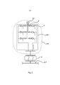
[0031] A Figura 1 representa um diagrama esquemático de um exemplo de um sistema de energia CC 1. O sistema de energia CC 1 compreende um barramento CC principal 3 que tem uma primeira barra coletora 3-1 e uma segunda barra coletora 3-2 separadas por meio de um disjuntor de interligação de barramentos 5, uma primeira unidade de geração de energia P1, uma segunda unidade de geração de energia P2, uma terceira unidade de geração de energia P3, uma quarta unidade de geração de energia P4, uma unidade de armazenamento de energia E, um primeiro acionamento D1 e um segundo acionamento D2.[0031] Figure 1 represents a schematic diagram of an example of a DC power system 1. The DC power system 1 comprises a
[0032] A primeira unidade de acionamento D1 e a segunda unidade de acionamento D2 estão dispostas para energizar motores elétricos e equipamentos similares. Exemplos de tais unidades de acionamento são os acionamentos únicos, os múltiplos acionamentos e os conversores de frequência estática destinada a suprir consumidores normais de CA com 50 Hz ou 60 Hz de potência CA.[0032] The first drive unit D1 and the second drive unit D2 are arranged to energize electric motors and similar equipment. Examples of such drive units are single drives, multiple drives and static frequency converters designed to supply normal AC consumers with 50 Hz or 60 Hz AC power.
[0033] O sistema de energia CC 1 compreende adicionalmente um comutador isolante 7, isto é, chaves seccionadoras associadas a uma unidade de geração de energia P1, P2, P3, P4 respectiva para ser capaz de desconectar as unidades de geração de energia P1, P2, P3, P4 do barramento CC principal 3. Através disso, cada unidade de geração de energia pode ser isolada de uma falha no, por exemplo, barramento CC principal 3, ou as mesmas podem ser isoladas para fins de manutenção.[0033] The DC power system 1 further comprises an isolating switch 7, i.e. disconnect switches associated with a respective power generation unit P1, P2, P3, P4 to be able to disconnect the power generation units P1, P2, P3, P4 of
[0034] A primeira unidade de geração de energia P1 é disposta para alimentar o barramento CC principal 3 e é conectável ao barramento CC principal 3 através de um comutador isolante 7. De acordo com o exemplo na Figura 1, a primeira unidade de geração de energia P1 é conectada à primeira barra coletora 3-1.[0034] The first power generation unit P1 is arranged to power the
[0035] A segunda unidade de geração de energia P2 está disposta para alimentar o barramento CC principal 3 e é conectável ao barramento CC principal 3 através de um comutador isolante 7. De acordo com o exemplo na Figura 1, a segunda unidade de geração de energia P2 é conectável à primeira barra coletora 3-1.[0035] The second power generation unit P2 is arranged to power the
[0036] A terceira unidade de geração de energia P3 é disposta para alimentar o barramento CC principal 3 e é conectável ao barramento CC principal 3 através de um comutador isolante 7. De acordo com o exemplo na Figura 1, a terceira unidade de geração de energia P3 é conectável à segunda barra coletora 3-2.[0036] The third power generation unit P3 is arranged to power the
[0037] A quarta unidade de geração de energia P4 é disposta para alimentar o barramento CC principal 3 e é conectável ao barramento CC principal 3 por meio de um comutador isolante 7. De acordo com o exemplo na Figura 1, à quarta unidade de geração de energia P1 é conectável à segunda barra coletora 3-2.[0037] The fourth power generation unit P4 is arranged to power the
[0038] A primeira unidade de geração de energia P1 compreende um gerador G1, tal como um gerador acionado por motor a diesel, disposto para gerar corrente alternada e um reparador R1 disposto para converter a corrente alternada para corrente contínua para ser alimentada para o barramento CC principal 3. O reparador R1 pode ser dotado de fusíveis dimensionados para explodir em caso de falha no reparador R1.[0038] The first power generation unit P1 comprises a generator G1, such as a diesel engine driven generator, arranged to generate alternating current and a repairer R1 arranged to convert alternating current to direct current to be fed to the
[0039] A segunda unidade de geração de energia P2, a terceira unidade de geração de energia P3 e a quarta unidade de geração de energia P4 podem ter um projeto similar ao da unidade de geração de energia P1. Para esse fim, cada uma dentre a segunda unidade de geração de energia P2, a terceira unidade de geração de energia P3 e a quarta unidade de geração de energia P4 pode compreender um gerador G2, G3, G4 respectivo e um reparador R2, R3, R4 respectivo para fornecer sinais CC para o barramento CC principal 3. No entanto, nota-se que uma combinação de diferentes tipos de geradores é possível com o mesmo sistema.[0039] The second power generation unit P2, the third power generation unit P3 and the fourth power generation unit P4 may have a similar design as the power generation unit P1. To that end, each of the second power generating unit P2, the third power generating unit P3 and the fourth power generating unit P4 may comprise a respective G2, G3, G4 generator and a R2, R3 repairer. Respective R4 to supply DC signals to the
[0040] Cada uma dentre a primeira unidade de acionamento D1 e a segunda unidade de acionamento D2 tem um sistema de barramento de unidade de acionamento DB em que compreende um primeiro barramento DB1 e um segundo barramento DB2. Além disso, cada uma dentre a primeira unidade de acionamento D1 e a segunda unidade de acionamento D2 tem várias unidades de conversão, como exemplificado a seguir pelos inversores I1, I2, I3, conectados ao respectivo sistema de barramento da unidade de acionamento do mesmo DB, e fusíveis F dispostos entre os terminais e os inversores I1, I2, I3 e o sistema de barramento da unidade de acionamento DB. Um exemplo de um inversor adequado é o inversor ACS800 da ABB.[0040] Each of the first D1 drive unit and the second D2 drive unit has a DB drive unit bus system in which it comprises a first DB1 bus and a second DB2 bus. In addition, each of the first D1 drive unit and the second D2 drive unit has several conversion units, as exemplified below by inverters I1, I2, I3, connected to the respective drive unit bus system of the same DB , and fuses F arranged between the terminals and the inverters I1, I2, I3 and the bus system of the DB drive unit. An example of a suitable drive is ABB's ACS800 drive.
[0041] Cada uma dentre a primeira unidade de acionamento D1 e a segunda unidade de acionamento D2 tem, adicionalmente, um primeiro tipo de unidade de entrada 17 que em uma extremidade está disposta para conexão com o barramento CC principal 3. A essa outra extremidade o primeiro tipo de unidade de entrada 17 é conectada ao sistema de barramento da unidade de acionamento DB. O primeiro tipo de unidade de entrada 17 compreende um comutador isolante disposto para desconectar a unidade de acionamento D1, D2 do barramento CC principal 3 e um dispositivo de bloqueio de corrente 11 que é capaz de bloquear o fluxo de corrente em uma direção do sistema de barramento da unidade de acionamento DB para o barramento CC principal 3 e permitir que a corrente flua em uma direção do barramento CC principal 3 para o sistema de barramento da unidade de acionamento DB. Tal dispositivo de bloqueio de corrente pode ser um dispositivo semicondutor tais como um diodo ou vários diodos, ou um transitor de porta bipolar (IGBT), tiristor, ou dispositivos similares.[0041] Each of the first drive unit D1 and the second drive unit D2 additionally has a first type of
[0042] Nota-se que, dependendo da aplicação, as unidades de acionamentos podem ser projetadas com diferentes números de inversores, de um inversor a uma pluralidade de inversores. Além disso, o primeiro tipo de unidade de acionamento pode, em uma modalidade, compreender uma unidade de comutação semicondutora conectada de forma antiparalela ao dispositivo de bloqueio de corrente, permitindo, assim, uma alimentação reversa de potência durante uma operação normal do sistema de energia CC. Tal unidade de comutação semicondutora pode, por exemplo, ser um transitor de porta bipolar (IGBT).[0042] Note that, depending on the application, the drive units can be designed with different numbers of inverters, from one inverter to a plurality of inverters. In addition, the first type of drive unit may, in one embodiment, comprise a semiconductor switching unit antiparallel connected to the current blocking device, thus allowing for a reverse power supply during normal operation of the power system. CC Such a semiconductor switching unit can, for example, be a bipolar gate transistor (IGBT).
[0043] A unidade de armazenamento de energia E tem um sistema de barramento da unidade de armazenamento de energia EB que tem um primeiro barramento EB1 e um segundo barramento EB2. A unidade de armazenamento de energia E compreende adicionalmente unidades de fornecimento de energia tais como unidade de bateria B e um banco condensador C conectado ao sistema de barramento da unidade de armazenamento de energia EB, um conversor CC-CC 15 conectado ao sistema de barramento da unidade de armazenamento de energia EB, e fusíveis F. Os fusíveis F são dispostos entre os terminais do conversor CC-CC 15 e o sistema de barramento da unidade de armazenamento de energia EB, entre o banco condensador C e o sistema de barramento da unidade de armazenamento de energia EB, e entre a unidade de bateria B e o sistema de barramento da unidade de armazenamento de energia EB.[0043] The energy storage unit E has a bus system of the energy storage unit EB which has a first bus EB1 and a second bus EB2. The energy storage unit E further comprises energy supply units such as the battery unit B and a capacitor bank C connected to the bus system of the energy storage unit EB, a CC-
[0044] Por meio do conversor CC-CC 15, o nível de tensão da saída da unidade de bateria B pode ser controlado se a potência for fornecida para o barramento CC principal 3 a partir da unidade de armazenamento de energia E.[0044] By means of the DC-
[0045] Deve-se notar que a unidade de armazenamento de energia E é um exemplo de muitas possibilidades de configurações relativas ao número de unidades de fornecimento de energia e conversores. Por exemplo, algumas variações da unidade de armazenamento de energia E não tem um banco de condensadores. O objetivo geral de um banco de condensadores na unidade de armazenamento de energia é contribuir em fusíveis fundidos no caso de uma falha interna.[0045] It should be noted that the energy storage unit E is an example of many possible configurations relating to the number of power supply units and converters. For example, some variations of energy storage unit E do not have a capacitor bank. The general purpose of a bank of capacitors in the energy storage unit is to contribute to blown fuses in the event of an internal failure.
[0046] A unidade de armazenamento de energia E tem adicionalmente um segundo tipo de unidade de entrada 9 que em uma extremidade é disposta para se conectar ao barramento CC principal 3. Na outra extremidade do mesmo, o segundo tipo de unidade de entrada 9 é conectado ao sistema de barramento da unidade de armazenamento de energia EB. O segundo tipo de unidade de entrada 9 compreende um comutador isolante para desconectar a unidade de armazenamento de energia E do barramento CC principal 3, uma unidade de comutação semicondutora 13 e um dispositivo de bloqueio de corrente 11 que é capaz de bloquear o fluxo de corrente na direção do sistema de barramento da unidade de armazenamento de energia EB para o barramento CC principal 3 e para permitir que a corrente flua na direção a partir do barramento CC principal 3 para o sistema de barramento da unidade de armazenamento de energia EB. Tal dispositivo de bloqueio de corrente pode ser um dispositivo semicondutor tais como um diodo ou vários diodos, ou um IGBT, um tiristor, ou dispositivos similares. A unidade de comutação semicondutora 13 pode, por exemplo, ser um IGBT. A unidade de comutação semicondutora 13 e o dispositivo de bloqueio de corrente 11 podem ser dispostos de forma antiparalela, com isso permite que a corrente flua na direção a partir do sistema de barramento da unidade de armazenamento de energia EB para o barramento CC principal 3 se o dispositivo de comutador semicondutor 13 for definido em seu estado saturado ou aberto por meio de sinais de controle apropriado. Por conseguinte, por meios do dispositivo de bloqueio de corrente 11 e a unidade de comutação semicondutora 13, a corrente pode seletivamente permitir o desvio do dispositivo de bloqueio de corrente e o fluxo para o barramento CC principal 3.[0046] The energy storage unit E additionally has a second type of
[0047] A Figura 2 é um diagrama esquemático da unidade de geração de energia P1. Os componentes internos do reparador R1 são mostrados. Para cada fase elétrica, o sinal de CA gerado pelo gerador G1 é fornecido para cada membro respectivo do reparador R1. Os dispositivos de comutador T são fornecidos para cada membro em que o dispositivo de comutador T pode ser controlado de forma que um sinal de CC possa ser emitido pelo reparador R1. No exemplo na Figura 2, os dispositivos de comutador são exemplificados por tiristores, embora outros meios de comutador também sejam possíveis, por exemplo, IGBTs. Além disso, o reparador R1 compreende fusíveis F para proteção do reparador R1 em caso de falha, isto é, um curto-circuito no reparador R1. Nesse caso, um ou mais dos fusíveis serão explodidos em resposta às correntes de falha que fluem para a falha através dos fusíveis F. No exemplo na Figura 2, cada dispositivo de comutador T está associado a um fusível F. Dessa forma, cada membro, isto é, cada fase, está associada a dois fusíveis F. Outras possibilidades de realizações da unidade de geração de energia P1 inclui um pé-de-cabra projetado junto com um diodo sob diodo em polo positivo dos terminais reparadores CC. A ideia geral é que se ocorrer uma falha interna, o reparador com o gerador se isolará do sistema de energia CC para minimizar as consequências para o sistema amplo.[0047] Figure 2 is a schematic diagram of power generation unit P1. Internal components of repairer R1 are shown. For each electrical phase, the AC signal generated by generator G1 is supplied to each respective member of repairer R1. T-switch devices are provided for each member where the T-switch device can be controlled so that a CC signal can be emitted by repairer R1. In the example in Figure 2, switching devices are exemplified by thyristors, although other switching means are also possible, for example IGBTs. In addition, the repairer R1 comprises F fuses for protection of the repairer R1 in case of failure, ie a short-circuit in the repairer R1. In this case, one or more of the fuses will blow in response to the fault currents flowing to the fault through fuses F. In the example in Figure 2, each switch device T is associated with a fuse F. that is, each phase is associated with two fuses F. Other possible realizations of the power generating unit P1 include a designed crowbar together with a diode under a diode on the positive pole of the DC repair terminals. The general idea is that if an internal failure occurs, the repairer with the generator will isolate itself from the DC power system to minimize the consequences for the wider system.
[0048] Os fusíveis F no reparador são vantajosamente dimensionados de modo que os mesmos não explodam quando sujeitos a correntes de falha como um resultado de falhas a jusante do reparador. O termo a jusante dever ser entendido em relação a um fluxo de corrente na direção do sistema de energia CC l.[0048] Fuses F in the repairer are advantageously dimensioned so that they do not explode when subjected to fault currents as a result of faults downstream of the repairer. The term downstream is to be understood in relation to a flow of current towards the DC power system l.
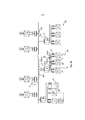
[0049] A Figura 3a é um exemplo de uma situação em que uma falha 19 ocorre no sistema de energia CC 1. No exemplo da Figura 3a, a falha 19 é um curto-circuito e ocorreu no barramento CC principal 3. A falha 19 é, por conseguinte, uma falha total. Várias estratégias de tratamento de falha são possíveis nesse caso.[0049] Figure 3a is an example of a situation where fault 19 occurs in DC power system 1. In the example of Figure 3a, fault 19 is a short circuit and occurred in
[0050] Em ambos os casos, devido à falha 19, as correntes de falha 20-1, 20-2, 20-3, 20-4 fluem para o lugar da falha 19, que é na primeira barra coletora 3-1 nesse exemplo. Em geral, a falha 19 é detectada por, pelo menos, uma pluralidade de sensores de monitoramento do sistema de energia CC 1, por exemplo, sensores de medição de corrente.[0050] In both cases, due to fault 19, fault currents 20-1, 20-2, 20-3, 20-4 flow to the place of fault 19, which is in the first busbar 3-1 in this example. In general, fault 19 is detected by at least a plurality of monitoring sensors of the DC power system 1, for example current measuring sensors.
[0051] De acordo com uma estratégia para tratar a falha, o disjuntor de interligação 5 gera o comando aberto como falha detectada. A parte sã, isto é, a segunda barra coletora 3-2 reinicia após a compartimentação. Assim, uma vez que o sistema de energia CC tenha dividido a parte sã, retoma a operação. O lado defeituoso, isto é, a primeira barra coletora 3-1, se ciente da localização das falhas, não reiniciará. Se não estiver ciente da localização, devido à falta de informação, o lado defeituoso tentaria um reinício para a detecção da falha.[0051] According to a strategy to handle the fault, the
[0052] Em outra versão da estratégia, os retificadores R1, R2, R3, R4 das unidades de geração de energia P1-P4 são controlados de forma que a saída de correntes dos mesmos tende a zero, e qualquer outra fonte de energia poderia também limitar a corrente no sistema de energia CC enquanto gera o comando aberto para o disjuntor de interligação 5. Uma vez que o sistema é divido, a parte sã detectar que a falha é eliminada, enquanto o lado defeituoso verá persistir a falha. Isso causará fontes de energia, por exemplo, a unidades de geração de energia no lado defeituoso para bloquear a corrente na falha.[0052] In another version of the strategy, the rectifiers R1, R2, R3, R4 of the P1-P4 power generation units are controlled so that their current output tends to zero, and any other energy source could also limit the current in the DC power system while generating the open command for the
[0053] Ainda em outra versão da estratégia, as fontes de energia podem limitar sua tensão de saída e as correntes a um nível que permitisse que um comutador isolante operasse dentro de suas classificações, em que o comutador isolante 7 possa desconectar a unidade de geração de energia do barramento CC principal 3.[0053] In yet another version of the strategy, power sources can limit their output voltage and currents to a level that would allow an isolating switch to operate within its ratings, where isolating switch 7 can disconnect the generation unit main DC
[0054] A primeira unidade de acionamento D1 e a segunda unidade de acionamento D2 não contribuem ou, pelo menos, contribuem minimamente para a corrente de falha devido à característica de bloqueio de corrente do dispositivo de bloqueio de correntes 11. Além disso, devido ao comutador isolante do primeiro tipo de unidade de entradas 17, a primeira unidade de acionamento D1 e a segunda unidade de acionamento D2 podem ser desconectadas do barramento CC principal 3. Com isso, cada uma dentre a primeira unidade de acionamento D1 e a segunda unidade de acionamento D2 pode ser protegida no caso de uma falha no barramento CC principal 3.[0054] The first drive unit D1 and the second drive unit D2 do not contribute or at least minimally contribute to the fault current due to the current blocking characteristic of the
[0055] A unidade de armazenamento de energia E é, também, protegida durante a falha 19 no barramento CC principal 3. Se a unidade de armazenamento de energia E estiver na fase intermediária do fornecimento de energia ao barramento CC principal 3 antes da ocorrência da falha 19, a corrente de saída do conversor CC-CC 15 pode ser controlada, por exemplo, definida como zero. Através disso, a unidade de armazenamento de energia E pode ser isolada do barramento CC principal 3 por meio de comutador isolante do segundo tipo de unidade de entrada 9. Além disso, antes da unidade de armazenamento de energia E ser isolada do barramento CC principal 3, o segundo tipo de unidade de entrada 9 pode bloquear a corrente de fluir para a falha 19. Isso é obtido por meio de dispositivo de bloqueio de corrente 11 do segundo tipo de unidade de entrada 9 e pela definição da unidade de comutação semicondutora 13 em seu estado desligado.[0055] Energy storage unit E is also protected during fault 19 on
[0056] Por meio das propriedades de bloqueio de corrente do primeiro tipo do dispositivo de entrada 17 e o segundo tipo de dispositivo de entrada 9, as correntes de falha para a falha 19 podem ser reduzidas.[0056] By means of the current blocking properties of the first type of
[0057] Com referência à Figura 3b, a situação em que a falha 22 ocorreu na primeira unidade de acionamento D1 será agora descrita. Essa falha é, por conseguinte, um lugar de falha na primeira unidade de acionamento D1.[0057] With reference to Figure 3b, the situation where fault 22 occurred in the first drive unit D1 will now be described. This failure is therefore a place of failure in the first drive unit D1.
[0058] De acordo com o exemplo na Figura 3b, um curto-circuito ocorreu no sistema de barramento da unidade de acionamento DB. O primeiro barramento DB-1 e o segundo barramento DB-2 podem, por exemplo, ser curto-circuito. Quando a falha 22 ocorre, as correntes 231, 23-2, 23-3, 23-4 e 23-5 fluem para a falha 22. As correntes 23-3, 234, 23-5 são fornecidas por banco de capacitores nos inversores I1, I2, I3. Como as correntes 23-3, 23-4, 23-5 fornecidas pelos bancos de capacitores fluem através dos fusíveis F dispostos na primeira unidade de acionamento D1, os fusíveis F provavelmente irão explodir, com isso desconectando os inversores I1, I2, I3 das falhas 22. A carga conectada aos inversores I1, I2, I3 é, com isso, desconectada do sistema de barramento da unidade de acionamento DB. Como a corrente das unidades de geração de energia P1, P2, P3, P4 é reduzida, por exemplo, por controle apropriado dos retificadores R1, R2, R3, R4, o comutador isolante do primeiro tipo de unidade de entrada 17 da primeira unidade de acionamento D1 pode ser desconectada da primeira unidade de acionamento D1 do barramento CC principal 3, e, por conseguinte, isolar a falha 22. Quando a falha 22 foi isolada, as partes restantes do sistema de energia CC 1 podem retomar a operação normal.[0058] According to the example in Figure 3b, a short circuit occurred in the bus system of the DB drive unit. The first DB-1 bus and the second DB-2 bus can, for example, be short-circuited. When fault 22 occurs, currents 231, 23-2, 23-3, 23-4 and 23-5 flow to fault 22. Currents 23-3, 234, 23-5 are supplied by capacitor banks in the drives I1, I2, I3. As the currents 23-3, 23-4, 23-5 supplied by the capacitor banks flow through the fuses F arranged in the first drive unit D1, the fuses F will probably blow, thereby disconnecting the inverters I1, I2, I3 from the faults 22. The load connected to inverters I1, I2, I3 is thus disconnected from the busbar system of the DB drive unit. As the current of the power generating units P1, P2, P3, P4 is reduced, for example, by proper control of the rectifiers R1, R2, R3, R4, the isolating switch of the first type of
[0059] Essencialmente, nenhuma corrente é fornecida para a falha 22 pelos bancos de capacitores da segunda unidade de acionamento D2 devido ao dispositivo de bloqueio de corrente 11 no primeiro tipo de unidade de entrada 17 da segunda unidade de acionamento D2.[0059] Essentially no current is supplied to fault 22 by the capacitor banks of the second drive unit D2 due to the
[0060] Além disso, o segundo tipo de unidade de entrada 9 da unidade de armazenamento de energia E pode bloquear o fluxo de corrente para a falha 22. Isso é obtido por meio de dispositivo de bloqueio de corrente 11 do segundo tipo de unidade de entrada 9 e definindo a unidade de comutação semicondutora 13 em seu estado desligado.[0060] Furthermore, the second type of
[0061] Por conseguinte, por meio de propriedades de bloqueio de corrente do primeiro tipo do dispositivo de entrada 17 e o segundo tipo do dispositivo de entrada 9, as correntes com falha para a falha 22 podem ser reduzidas.[0061] Therefore, by means of current blocking properties of the first type of
[0062] Em situações em que a falha ocorre a jusante de um inversor I1, I2, I3, tal falha é, tipicamente, tratada pelos fusíveis F daquele inversor.[0062] In situations where the fault occurs downstream of an inverter I1, I2, I3, such a fault is typically handled by the F fuses of that inverter.
[0063] Em geral, as falhas a jusante dos fusíveis dentro de uma unidade, tal como uma unidade de geração de energia, uma unidade de armazenamento de energia ou uma unidade de acionamento, são manuseadas pelos fusíveis daquela unidade.[0063] In general, failures downstream of fuses within a unit, such as a power generating unit, an energy storage unit or a drive unit, are handled by the fuses of that unit.
[0064] O sistema de energia CC descrito no presente documento pode ser vantajosamente usado como um sistema de energia incorporado para energizar uma embarcação, ou como um sistema de energia em outros espaços confinados onde disjuntores grandes CC são indesejáveis. O presente sistema de energia CC é tipicamente usado em um ambiente de baixa tensão, embora as aplicações de voltagens mais elevadas, por exemplo, de tensão média também sejam previstas.[0064] The DC power system described in this document can be advantageously used as an embedded power system to power a vessel, or as a power system in other confined spaces where large DC circuit breakers are undesirable. The present DC power system is typically used in a low voltage environment, although higher voltage applications, eg medium voltage, are also anticipated.
[0065] O conceito inventivo foi descrito acima principalmente com referência a alguns exemplos. No entanto, conforme é facilmente percebido por um versado na técnica, outras modalidades além daquelas reveladas acima são igualmente possíveis dentro do escopo do conceito inventivo, conforme definido pelas concretizações anexas. Por exemplo, um sistema de energia CC de acordo com a presente revelação pode incluir menos ou mais unidades de geração de energias do que no exemplo descrito na Figura 1. Além disso, o sistema de energia CC não precisa incluir uma unidade de armazenamento de energia ou pode incluir unidades de armazenamento de energia adicionais e/ou menos ou mais unidades de acionamento.[0065] The inventive concept has been described above mainly with reference to some examples. However, as is easily perceived by a person skilled in the art, other modalities than those disclosed above are equally possible within the scope of the inventive concept, as defined by the attached embodiments. For example, a DC power system in accordance with the present disclosure may include fewer or more power generation units than in the example described in Figure 1. Furthermore, the DC power system need not include an energy storage unit. or it can include additional energy storage units and/or fewer or more drive units.
Claims (11)
Applications Claiming Priority (3)
| Application Number | Priority Date | Filing Date | Title |
|---|---|---|---|
| EP12157487.5A EP2634885B1 (en) | 2012-02-29 | 2012-02-29 | A DC-power system with system protection capabilities |
| EP12157487.5 | 2012-02-29 | ||
| PCT/EP2013/051314 WO2013127575A1 (en) | 2012-02-29 | 2013-01-24 | A dc-power system with system protection capabilities |
Publications (3)
| Publication Number | Publication Date |
|---|---|
| BR112014019687A2 BR112014019687A2 (en) | 2017-06-20 |
| BR112014019687A8 BR112014019687A8 (en) | 2017-12-26 |
| BR112014019687B1 true BR112014019687B1 (en) | 2021-06-08 |
Family
ID=47603743
Family Applications (1)
| Application Number | Title | Priority Date | Filing Date |
|---|---|---|---|
| BR112014019687-7A BR112014019687B1 (en) | 2012-02-29 | 2013-01-24 | dc power system to power a vessel |
Country Status (14)
| Country | Link |
|---|---|
| US (1) | US9735573B2 (en) |
| EP (1) | EP2634885B1 (en) |
| JP (1) | JP6001098B2 (en) |
| KR (1) | KR101542339B1 (en) |
| CN (1) | CN104137372B (en) |
| AU (1) | AU2013225292B2 (en) |
| BR (1) | BR112014019687B1 (en) |
| CA (1) | CA2865231C (en) |
| DK (1) | DK2634885T3 (en) |
| ES (1) | ES2552857T3 (en) |
| HK (1) | HK1186850A1 (en) |
| RU (1) | RU2592066C2 (en) |
| SG (1) | SG11201404427UA (en) |
| WO (1) | WO2013127575A1 (en) |
Families Citing this family (28)
| Publication number | Priority date | Publication date | Assignee | Title |
|---|---|---|---|---|
| US9557794B2 (en) | 2014-11-07 | 2017-01-31 | General Electric Company | System and method for distributing electrical power |
| EP3035477A1 (en) | 2014-12-19 | 2016-06-22 | ABB Technology Ltd | A power system comprising a central energy storage system and a method of controlling power transfer in a power system |
| US9912151B2 (en) | 2015-01-23 | 2018-03-06 | General Electric Company | Direct current power system |
| US9853451B2 (en) * | 2015-01-30 | 2017-12-26 | General Electric Company | Direct current power system |
| JP6416707B2 (en) * | 2015-07-08 | 2018-10-31 | 東芝三菱電機産業システム株式会社 | Power conversion system |
| EP3148032B1 (en) | 2015-09-28 | 2018-03-28 | GE Energy Power Conversion Technology Ltd | Power supply system of a set of loads connected in parallel to a dc power bus |
| EP3203595A1 (en) * | 2016-02-05 | 2017-08-09 | Visedo Oy | An electric power system |
| EP3208909B1 (en) * | 2016-02-18 | 2019-08-14 | GE Energy Power Conversion Technology Ltd | Mixed ac-dc electrical power distribution system for supplying variable-frequency loads and fixed-frequency loads |
| WO2017163625A1 (en) * | 2016-03-25 | 2017-09-28 | シャープ株式会社 | Power generation system, power conditioner, power control device, power control method, and power control program |
| DK3282584T3 (en) * | 2016-08-11 | 2021-06-14 | Siemens Energy AS | Power distribution system and procedure |
| FR3055751B1 (en) * | 2016-09-02 | 2018-09-21 | Inst Supergrid | METHOD FOR CONTROLLING AN INSTALLATION FOR CONTINUOUS CURRENT TRANSPORT INTO A NETWORK WHILE PROTECTING SUCH A NETWORK ABOUT A SHORT CIRCUIT FAULT |
| DK3322057T3 (en) * | 2016-11-10 | 2021-12-20 | Abb Schweiz Ag | DC POWER SYSTEM DIVIDED INTO DIFFERENT PROTECTION AREAS |
| EP3379674B1 (en) * | 2017-03-21 | 2020-08-05 | Siemens Aktiengesellschaft | Power distribution system |
| EP3393029B1 (en) * | 2017-04-20 | 2019-07-03 | Danfoss Mobile Electrification Oy | A power converter and an electric power system |
| KR102176100B1 (en) | 2017-05-23 | 2020-11-09 | 엘에스일렉트릭(주) | Power converting apparatus |
| EP3407449A1 (en) * | 2017-05-24 | 2018-11-28 | Siemens Aktiengesellschaft | Redundant direct current network |
| EP3407459A1 (en) * | 2017-05-25 | 2018-11-28 | Siemens Aktiengesellschaft | Power supply system and method |
| CN110571781B (en) * | 2018-06-05 | 2022-10-21 | 台达电子工业股份有限公司 | DC bus voltage control method and system |
| JP2021536219A (en) * | 2018-09-13 | 2021-12-23 | エルエス、エレクトリック、カンパニー、リミテッドLs Electric Co., Ltd. | Power supply system |
| KR102336317B1 (en) * | 2018-09-13 | 2021-12-07 | 엘에스일렉트릭 (주) | System for supplying power |
| EP3852228A4 (en) * | 2018-09-13 | 2022-08-10 | LS Electric Co., Ltd. | Method for controlling power suppply system |
| KR102299860B1 (en) * | 2018-09-13 | 2021-09-09 | 엘에스일렉트릭 (주) | Module for supplying power and system for supplying power |
| KR102407417B1 (en) * | 2018-09-13 | 2022-06-10 | 엘에스일렉트릭(주) | Module for supplying power and system for supplying power |
| WO2020200495A1 (en) * | 2019-03-29 | 2020-10-08 | Siemens Aktiengesellschaft | Electric grid and method for operating an electric grid |
| US11923674B2 (en) | 2019-03-29 | 2024-03-05 | Siemens Aktiengesellschaft | Method and apparatus for controlling solid state circuit breaker, and solid state circuit breaker |
| CN114400643B (en) * | 2021-12-25 | 2024-02-23 | 智寰(北京)氢能科技有限公司 | Stable flexible direct-current power grid topological structure |
| CN114336539B (en) * | 2021-12-31 | 2024-02-23 | 苏州汇川控制技术有限公司 | Short-circuit protection device determining method, short-circuit protection circuit, equipment and storage medium |
| JP2023114249A (en) * | 2022-02-04 | 2023-08-17 | 三菱重工業株式会社 | Direct current micro grid, direct current micro grid system, control method, and program |
Family Cites Families (35)
| Publication number | Priority date | Publication date | Assignee | Title |
|---|---|---|---|---|
| BE559130A (en) * | 1956-07-12 | 1900-01-01 | Westinghouse Electric Corp | |
| US3254290A (en) * | 1963-01-16 | 1966-05-31 | Westinghouse Electric Corp | Protective means for rectifier apparatus |
| CH468735A (en) * | 1966-09-13 | 1969-02-15 | Bbc Brown Boveri & Cie | Device with inverter for feeding asynchronous motors |
| US3887860A (en) | 1972-11-15 | 1975-06-03 | Eaton Corp | Fuseless inverter |
| CA2183176C (en) * | 1995-08-18 | 2000-10-24 | Brian R. Pelly | High power dc blocking device for ac and fault current grounding |
| DE19610800C1 (en) * | 1996-03-19 | 1997-07-24 | Siemens Ag | Fault-tolerant traction drive converter for rail vehicles |
| JP4124855B2 (en) * | 1998-03-16 | 2008-07-23 | 東芝三菱電機産業システム株式会社 | Ship power supply |
| US20030071633A1 (en) * | 2001-10-16 | 2003-04-17 | Fedirchuk David James | Bus fault protection unit for an electrical power system |
| US6909942B2 (en) * | 2002-02-25 | 2005-06-21 | General Electric Company | Method for power distribution system components identification, characterization and rating |
| US20040102109A1 (en) * | 2002-09-18 | 2004-05-27 | Cratty William E. | DC power system for marine vessels |
| JP2004338577A (en) | 2003-05-16 | 2004-12-02 | Hitachi Ltd | Power supply device and method for vehicle |
| US7344202B2 (en) * | 2005-05-11 | 2008-03-18 | General Electric Company | System and method for dealing with ground fault conditions that can arise in an electrical propulsion system |
| US20070002506A1 (en) | 2005-06-30 | 2007-01-04 | General Electric Company | Circuit protection system |
| DE102005031833B4 (en) | 2005-07-06 | 2017-01-05 | Phoenix Contact Gmbh & Co. Kg | Method and electronic power supply device for supplying power to a low-voltage load protected by a protective device |
| JP4367391B2 (en) | 2005-09-01 | 2009-11-18 | トヨタ自動車株式会社 | Charge control device and electric vehicle |
| US8310094B2 (en) | 2006-01-27 | 2012-11-13 | Sharp Kabushiki Kaisha | Power supply system |
| JP5028049B2 (en) * | 2006-08-17 | 2012-09-19 | シャープ株式会社 | Solar power system |
| GB0606904D0 (en) * | 2006-04-06 | 2006-05-17 | Rolls Royce Plc | Electrical Fault Detection |
| US7614164B2 (en) | 2006-04-07 | 2009-11-10 | Seychelles Imports, Llc | Shoe with padded sole |
| RU2321124C1 (en) * | 2006-08-22 | 2008-03-27 | Государственное образовательное учреждение высшего профессионального образования "Сибирский государственный университет телекоммуникаций и информатики" (ГОУ ВПО "СибГУТИ") | Method for surge protection of dc electric mains |
| GB2443002A (en) | 2006-10-16 | 2008-04-23 | Converteam Ltd | dc power distribution system |
| US7710081B2 (en) | 2006-10-27 | 2010-05-04 | Direct Drive Systems, Inc. | Electromechanical energy conversion systems |
| US20100097736A1 (en) * | 2006-12-14 | 2010-04-22 | Alexander Apostolov | Method and an apparatus for protecting a bus in a three-phase electrical power system |
| US7980905B2 (en) * | 2007-11-25 | 2011-07-19 | C-Mar Holdings, Ltd. | Method and apparatus for providing power to a marine vessel |
| US8062081B2 (en) * | 2007-12-12 | 2011-11-22 | Foss Maritime Company, Inc. | Hybrid propulsion systems |
| CA2707498A1 (en) * | 2007-12-12 | 2009-06-18 | Alan Mcdonnell | Electric power distribution methods and apparatus |
| DE102008050543A1 (en) | 2008-10-06 | 2010-04-15 | Siemens Aktiengesellschaft | Protection circuit for a DC link of an inverter, in particular a solar inverter, against overvoltages |
| BRPI0922960A2 (en) * | 2008-12-12 | 2016-01-26 | Abb Research Ltd | system and apparatus for transferring energy to vessels |
| NZ594132A (en) | 2008-12-19 | 2014-01-31 | Protectelec Pty Ltd | A sentinel unit for an it electrical distribution system having a floating reference conductor |
| US8208276B2 (en) | 2009-02-20 | 2012-06-26 | Toshiba Mitsubishi-Electric Indsutrial Systems Corporation | Power conversion device |
| GB2468652B (en) * | 2009-03-16 | 2011-08-31 | Ge Aviat Systems Ltd | Electrical power distribution |
| EP2293407A1 (en) * | 2009-09-08 | 2011-03-09 | Converteam Technology Ltd | Power transmission and distribution systems |
| CA2798650C (en) * | 2010-05-11 | 2016-05-03 | Abb Technology Ag | A plant for transmitting high voltage dc electric power including overvoltage protection |
| EP2503666A3 (en) * | 2011-02-01 | 2013-04-17 | Siemens Aktiengesellschaft | Power supply system for an electrical drive of a marine vessel |
| US9048694B2 (en) * | 2012-02-01 | 2015-06-02 | Abb Research Ltd | DC connection scheme for windfarm with internal MVDC collection grid |
-
2012
- 2012-02-29 ES ES12157487.5T patent/ES2552857T3/en active Active
- 2012-02-29 EP EP12157487.5A patent/EP2634885B1/en active Active
- 2012-02-29 DK DK12157487.5T patent/DK2634885T3/en active
-
2013
- 2013-01-24 JP JP2014559135A patent/JP6001098B2/en not_active Expired - Fee Related
- 2013-01-24 CA CA2865231A patent/CA2865231C/en not_active Expired - Fee Related
- 2013-01-24 CN CN201380010856.0A patent/CN104137372B/en active Active
- 2013-01-24 WO PCT/EP2013/051314 patent/WO2013127575A1/en active Application Filing
- 2013-01-24 SG SG11201404427UA patent/SG11201404427UA/en unknown
- 2013-01-24 BR BR112014019687-7A patent/BR112014019687B1/en active IP Right Grant
- 2013-01-24 RU RU2014138818/07A patent/RU2592066C2/en active
- 2013-01-24 KR KR1020147024362A patent/KR101542339B1/en active IP Right Grant
- 2013-01-24 AU AU2013225292A patent/AU2013225292B2/en not_active Ceased
- 2013-12-19 HK HK13114097.8A patent/HK1186850A1/en not_active IP Right Cessation
-
2014
- 2014-08-27 US US14/470,182 patent/US9735573B2/en active Active
Also Published As
| Publication number | Publication date |
|---|---|
| JP6001098B2 (en) | 2016-10-05 |
| HK1186850A1 (en) | 2014-03-21 |
| AU2013225292A1 (en) | 2014-07-24 |
| US9735573B2 (en) | 2017-08-15 |
| CA2865231C (en) | 2016-03-01 |
| US20140361621A1 (en) | 2014-12-11 |
| DK2634885T3 (en) | 2015-11-23 |
| JP2015515243A (en) | 2015-05-21 |
| WO2013127575A1 (en) | 2013-09-06 |
| RU2592066C2 (en) | 2016-07-20 |
| KR101542339B1 (en) | 2015-08-05 |
| CA2865231A1 (en) | 2013-09-06 |
| CN104137372A (en) | 2014-11-05 |
| AU2013225292B2 (en) | 2016-04-21 |
| KR20140123982A (en) | 2014-10-23 |
| ES2552857T3 (en) | 2015-12-02 |
| SG11201404427UA (en) | 2014-10-30 |
| BR112014019687A8 (en) | 2017-12-26 |
| EP2634885A1 (en) | 2013-09-04 |
| CN104137372B (en) | 2016-10-12 |
| EP2634885B1 (en) | 2015-09-02 |
| RU2014138818A (en) | 2016-04-20 |
| BR112014019687A2 (en) | 2017-06-20 |
Similar Documents
| Publication | Publication Date | Title |
|---|---|---|
| BR112014019687B1 (en) | dc power system to power a vessel | |
| ES2856832T3 (en) | Converter layout and procedure for its protection against short circuits | |
| JP5797751B2 (en) | Voltage inverter and method for controlling such an inverter | |
| BR102015016616B1 (en) | Power system for marine vessel and method of supplying power to a marine vessel | |
| EP2471164B1 (en) | Converter cell module with autotransformer bypass, voltage source converter system comprising such a module and a method for controlling such a system | |
| BR102016000759A2 (en) | direct current power system and method for direct current power supply | |
| ES2898710T3 (en) | A separate DC power system in different protection zones | |
| AU2018238950B2 (en) | Power distribution system | |
| JP5963026B2 (en) | DC supply unit for power supply unit | |
| CN105896477A (en) | Ground protection method of modular multilevel converter and modular multilevel converter | |
| ES2360463T3 (en) | SEPARATION DEVICE FOR A VOLTAGE SEMICONDUCTOR AND OPERATING PROCEDURE OF THE SAME, POWER MODULE AND SYSTEM ASSEMBLY. |
Legal Events
| Date | Code | Title | Description |
|---|---|---|---|
| B25A | Requested transfer of rights approved |
Owner name: ABB SCHWEIZ AG (CH) |
|
| B25L | Entry of change of name and/or headquarter and transfer of application, patent and certificate of addition of invention: publication cancelled |
Owner name: ABB TECHNOLOGY AG (CH) |
|
| B25C | Requirement related to requested transfer of rights |
Owner name: ABB TECHNOLOGY AG (CH) |
|
| B25L | Entry of change of name and/or headquarter and transfer of application, patent and certificate of addition of invention: publication cancelled |
Owner name: ABB SCHWEIZ AG (CH) Owner name: ABB SCHWEIZ AG (CH) Free format text: ANULADA A PUBLICACAO CODIGO 25.3 NA RPI NO 2457 DE 06/02/2018 POR TER SIDO INDEVIDA. |
|
| B25A | Requested transfer of rights approved |
Owner name: ABB SCHWEIZ AG (CH) |
|
| B06F | Objections, documents and/or translations needed after an examination request according [chapter 6.6 patent gazette] | ||
| B06U | Preliminary requirement: requests with searches performed by other patent offices: procedure suspended [chapter 6.21 patent gazette] | ||
| B25G | Requested change of headquarter approved |
Owner name: ABB SCHWEIZ AG (CH) |
|
| B09A | Decision: intention to grant [chapter 9.1 patent gazette] | ||
| B16A | Patent or certificate of addition of invention granted [chapter 16.1 patent gazette] |
Free format text: PRAZO DE VALIDADE: 20 (VINTE) ANOS CONTADOS A PARTIR DE 24/01/2013, OBSERVADAS AS CONDICOES LEGAIS. |